FE 'tkGooie' Utilities

'PHYSICStools' group

1D Collision of
Two Masses that
Stick Together

(no friction/energy losses)
(an animation
on a Tk 'canvas')
(FE = Freedom Environment)

FE 'tkGooie' interface to
simulate 2 colliding masses
that stick together

A larger, hi-res image is below.

FE Home Page > FE Downloads Page >

FE 'tkGooies' Description Page >

FE 'tkGooies' 'PHYSICStools' Page >

This
'tkAnimateCollisionOfTwoStickingMasses_1D'
Page

INTRODUCTION to Tcl-Tk script
'tkAnimateCollisionOfTwoStickingMasses_1D'

For at least 5 years now (about 2011 to 2016), I have had it on my Tk-scripts-to-do list to implement Tcl-Tk GUI scripts that perform numerical-integration of the ODE's ( ordinary differential equations ) that describe some dynamic physics configurations of classical mechanics --- as well as handling some non-physics applications.

I had in mind the differential equations describing

Recently (July 2016), I finally implemented a

Tk script to simulate a single oscillating pendulum.

The script integrates the 'nonlinear' second-order differential equation that can simulate the motion of a wide-swinging pendulum --- that is, there is no need to restrict the 'problem' to small angular oscillations of the pendulum.

That Tk GUI script allowed for animating a representation of a pendulum arm-and-bob --- on a Tk 'canvas' widget.

I also implemented a

Tk script to simulate a bouncing rigid ball

like a golf ball.

However, there are some other types of dynamic 'problems' in physics that do not require numerical integration of differential equations --- for a solution --- and for an animation.

That is, some physics 'problems' have an algebraic solution --- and that algebraic solution can be used to generate an animation of the components in the 'problem'.

Examples include collision problems of masses where it is assumed that there are no frictional losses --- and where the algebraic solution can be derived based on a physical 'law' such as conservation of momentum and/or conservation of energy.

One such 'problem' involves collision of 2 masses where the 2 masses separate, intact after the collision (Wikipedia link).

Another such 'problem' involves collsion of 2 masses where the 2 masses stick together after the collision (Wikipedia link).

There are many animated GIF files on the internet depicting these types of collisions for one specific case of the values of the masses and the initial velocities.

But I wanted to provide a 'tkGooie' by which the user can experiment with different mass values and initial velocity values.

I wanted to handle the case where the two masses are moving in the same direction (one over-taking the other) --- as well as the usual cases of masses moving toward one another --- or one mass being at rest.

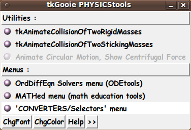
And I wanted to provide these new 'physics tools' via a new 'PHYSICStools' drawer in the main toolchest of the FE 'tkGooies' system:

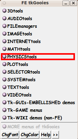
via a new 'PHYSICStools' toolchest:

I recently created a 'tkGooie' script for the first of these 2 collision 'problems'.

The script is available at a

'tkAnimateCollisionOfTwoRigidMasses_1D' page.

This page is intended to provide a Tk script for the 'collide-and-stick-together' situation.

This situation is reminiscent of the 'Giant Impact Theory' (Wikipedia link) which proposes that the Earth-Moon system may have been formed from an 'inelastic' collision in which 2 huge masses merged.

However, in that case, the masses did not stick together (totally).

A large fragment may have 'punched through' --- but gravity held one resulting mass fragment in orbit around the other.

That scenario brings to mind another haunting scenario --- a large meteor impact, like the one that may have wiped out the dinosaurs --- and the one that left a huge crater in Arizona --- and the one that is thought to have struck the Antarctic leaving a huge mass that causes a gravity anomoly under the ice and snow.

In fact, the animation provided by this script may be considered to model (approximately) the 'direct' impact of a large asteroid with the Earth --- and the resulting velocity of the combined Earth-and-asteroid mass.


NOTATION and EQUATIONS

The following notation is similar to that used in many physics documents:

  • m1 denotes mass 1

  • m2 denotes mass

  • V1b denotes velocity of mass1 BEFORE impact

  • V2b denotes velocity of mass2 BEFORE impact

  • Va denotes velocity of mass1+mass2 AFTER impact

The GUI should allow the user to specify m1, m2, V1b, V2b.

The GUI script then can use a single algebraic expression to calculate Va.

See equation below.

The 3 velocities V1b, V2b, Va are to be used to animate the motions of the two masses, before and after the collision.

We assume a 'conservative system'.

By that we mean that the motion and collision of the 2 masses are modeled under the following assumptions.

  • There is no energy loss during motion, such as frictional losses due to contact with a surface or losses due to air/fluid resistance.

  • There are no energy losses at impact, due to energy transfer into the masses, such as deformation and heat generation.

  • There is no energy loss due to sound generation (energy transfer to vibrating air molecules) due to the impact.

  • We ignore ('neglect') gravitational attraction effects.

    Although any two masses experience a gravitational attraction to each other, we assume that the velocity increments that would arise from such gravitational attraction are extremely small increments compared to the user-specified velocities.

    Essentially, we are considering relatively small masses.

The following equation gives the values of Va.

Va = (m1*V1b + m2*V2b) / (m1 + m2)

This equation is easily derived from the single equation for conservation of momentum:

m1*V1b + m2*V2b = (m1 + m2)*Va


MY GOALS FOR THE GUI:

The GUI should allow the user to enter various values for

  • m1

  • m2

  • V1b

  • V2b

  • D,
    the initial distance between m1 and m2.

In addition, the GUI should allow the user to specify the width of the image area in pixels, say ImgWidthPx.

The GUI should provide 2 buttons by which the user can specify 2 colors for:

  • the canvas background

  • the 2 masses (circles)
    and the line along which they travel.

When the mass and velocity parameters are ready, the GUI is to provide a 'Solve' button by which the user can trigger the calculation of the after-impact velocity, Va.

After Va is calculated and the user has readied the D parameter, image width (in pixels), and the 2 colors, the user can click on a 'Start' radiobutton to start the animation.

The user can click on a 'Stop' radiobutton to stop the animation, if it is still going.

The GUI is to include a 'Help' button by which the user can get information on how the GUI can be used.

And the GUI can include a 'ResetParms' button --- by which the user can reset the values of m1, m2, V1b, V2b, and D to their initially-displayed values.

---

To evaluate any further requirements that we may need for the GUI, it is helpful to know some of the details of

  • the method of implementing the animation

Some details follow.


SOME DETAILS OF THE ANIMATION PROCESS :

The details of doing the drawing of the animation get rather complicated because the user can specify positive or negative velocities.

If the 'before' velocities are both positive or both negative, it may take a long time for the impact to occur --- or impact may not be possible.

The animation logic needs to check for the latter situation.

To model the before-impact and after-impact movement within the image area, the time and place of the impact need to be computed.

Then limits, Xmin and Xmax, in 'world-coordinates' need to be computed so that the animation can be drawn in such a way that the before-impact and after-impact motion can be drawn within the specified image width.

The limits, Xmin and Xmax, in world-coordinates need to be mapped to the left and right pixel-coordinates, 0 and ImgWidthPx.

This will allow the before-impact, impact, and after-impact motion of the 2 masses to proceed within the image area.

A time-step size, h, may be automatically computed for the user in order that the animation proceeds smoothly.

The initial distance, D, between the 2 masses may need to be adjusted to avoid an animation that proceeds too slowly.

In addition, we use the value of the 2 masses, m1 and m2, to determine the radii of the 2 circles that are drawn to indicate the magnitude of the 2 masses.

And we use the sum m1+m2 to determine a radius of a circle to represent the merged masses that result from the impact.

The way that these 3 radii are determined, in world-coordinates, can be rather involved.

See the comments in the 'animate' proc for details on the various aspects of implementing the animation.


THE GUI LAYOUT :

From the discussion above, we see that the Tk GUI should allow the user to specify

m1, m2, V1b, V2b

from which Va can be calculated.

There is to be a 'Solve' button --- to calculate Va.

---

For the animation, some other parameters are required.

For example: D, image-width, and 2 colors.

The GUI may allow the user to specify D ---- an initial distance between m1 and m2.

The GUI can let the user specify the width of the image area in pixels, say ImgWidthPx.

And the GUI can provide 2 buttons by which the user can specify 2 colors.

Then, on the GUI, there can be 'Start' and 'Stop' radiobuttons to start and stop an animation run.

The time-step and speed of animation:

    This script may use the velocities --- V1b, V2b, Va ---- to calculate a time-step, 'h', that gives smooth animation.

    (Thus we avoid the need to supply a widget on the GUI for time-step.)

    The time-step, 'h', may be used to control the real-time speed of the animation.

    To allow the user to speed-up or slow-down the animation, there could be a Tk widget ('entry' or 'scale') by which to specify a wait-time (in millisecs) between computing and displaying the new positions of the 2 circles.

    This would be an alternative to using a wait-time value calculated from the user-selected time-step, h.

    For now, we may simply calculate the animation wait-time based on the time-step, h.

We may also accumulate the animation data --- t(i), x1(t(i)), x2(t(i)), and x12(t(i)) where x1 and x2 denote the location of the 2 masses during the animation, before the impact --- and x12 denotes the location of the combined mass during the animation, after the impact.

A 'ShowList' button may be used to show a table of these values. This data could conceivably be used in other applications --- such as an 'xy' plot utility.

---

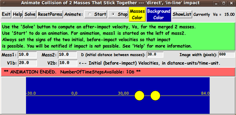
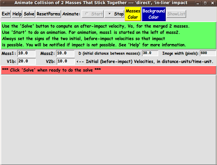
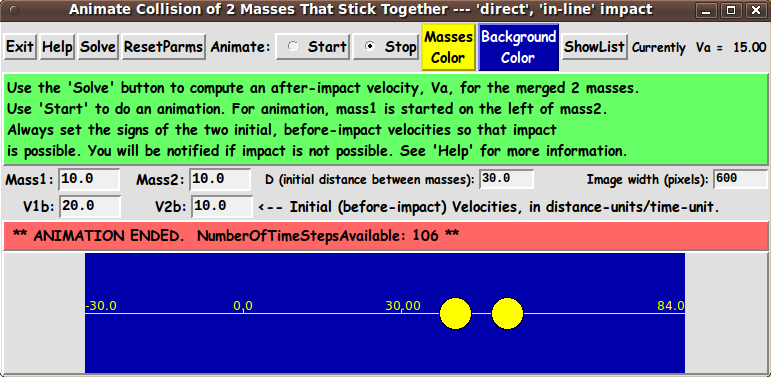
One way the user can specify all these parameters is indicated by the following 'sketch' of a layout for the GUI:

In the following sketch of the GUI:


   SQUARE BRACKETS indicate a comment (not to be placed on the GUI).
   BRACES          indicate a Tk 'button' widget.
   UNDERSCORES     indicate a Tk 'entry' widget.
   A COLON         indicates that the text before the colon is on a 'label' widget.
   CAPITAL-O       indicates a Tk 'radiobutton' widget.
   CAPITAL-X       indicates a Tk 'checkbutton' widget (if any).
   Vertical bars (and horizontal hyphens) outline a 'canvas' widget.
   
   If there are scrollbars:

   Less-than and greater-than signs indicate the left and right ends
   of a horizontal 'scrollbar'.

   Capital-V and Capital-A letters indicate the bottom and top ends
   of a vertical 'scrollbar'.


Here is the sketch:

FRAMEnames
VVVVVVVVVV
            ------------------------------------------------------------------------------------------
            Animate the Collision of Two Masses That Stick Together --- 'direct', 'in-line' impact
            [window title]
            ------------------------------------------------------------------------------------------

.fRbuttons   {Exit} {Help} {Solve} {Reset  Animate: O Start O Stop  {Masses  {Background  {Show
                                    Parms}                           Color}     Color}     List}

.fRguide     [ ... A description of the equation(s) or solution technique goes here, in a label widget.  ... ]

.fRmasses    Mass1: 10.0___  Mass2: 10.0___  D (distance between masses): 10.0__     Image width (pixels): 600__

.fRinit        V1b: 20.0___    V2b: -20.0___ <-- Initial (before impact) Velocities, in distance-units/time-unit    

.fRmsg       [ ..........  Messages go here, in a label widget .......................... ]

.fRcanvas    |-----------------------------------------------------------------------------|
             |                                                                             |
             |     [This area is to contain a non-scrollable canvas widget in which        |
             |      the animation is to be drawn.                                          |
             |                                                                             |
             |      The canvas widget is centered at the top of this area.]                |
             |                                                                             |
             |                                                                             |
             |                                                                             |
             |                                                                             |
             |-----------------------------------------------------------------------------|


GUI components:

From the GUI 'sketch' above, it is seen that this GUI layout consists of about

  • 7 button widgets
  • 10 label widgets
  • 6 entry widgets
  • 1 canvas widget with no scrollbars
  • 2 radiobutton widgets in 1 group
  • 0 scale widgets
    (but may use scale widgets in place of some entry widgets)
  • 0 checkbutton widgets
  • 0 listbox widgets
  • 0 text widgets

The GUI (a screenshot)

To implement this Tk GUI script, I fetched the 'tkAnimateCollisionOfTwoRigidMasses_1D' script that had most of these GUI elements.

I converted that script to a 'tkAnimateCollisionOfTwoStickingMasses_1D' script.

I ended up with the GUI seen in the following image.

This is the GUI as it first appears.

As the message in the middle of the GUI indicates, the user can take the defaults for all the parameters and simply click on the 'Solve' button to calculate the 'after-velocity', Va.

Then the user can click on the 'Start' radiobutton to start an animation based on the mass values, velocity values, and D.

After an animation, when I clicked on the 'ShowList' button, a list of computed results from the last animation --- time, x1, x2, x12 --- appeared for hundreds of time steps --- along with a display of the parameters used in the simulation.

---

Note that you can use the 'ShowList' button to generate columns of decimal numbers that can be copied-and-pasted into a text-editor window.

The text editor can be used to save the data to a text file.

Then that text file can be edited (to remove or comment out the header and trailer text) and fed into an FE 'tkGooie' 'PLOTtools' plot utility like the 'gnuplot' front-end at

tkGnuplotXY_2or3colsFromFile

to get a plot of the position functions versus time.

---

To give you an idea of what the animation image area looks like, below is a 'screenshot'.

Before clicking the 'Start' button for this animation, I could have used the 2 color buttons to call up a color selector GUI to set color of the masses to white and the background color to black, for example.

---

HELP TEXT

The 'Help' button on the GUI shows extensive text describing this utility, in a popup window with scrollbars for the text area.


DESCRIPTION OF THE CODE

Below I provide a link to the Tk script code for this
'tkAnimateCollisionOfTwoStickingMasses_1D' utility.

For this Tk script, I follow my usual 'canonical' structure for Tk code:


  0) Set general window & widget parms (win-name, win-position,
     win-color-scheme, fonts, widget-geometry-parms, win-size-control,
     text-array-for-labels-etc).

  1a) Define ALL frames (and sub-frames, if any).
  1b) Pack   ALL frames and sub-frames.

  2) Define & pack all widgets in the frames, frame by frame.
     Within each frame, define ALL the widgets. Then pack the widgets.

  3) Define keyboard and mouse/touchpad/touch-sensitive-screen action
     BINDINGS, if needed.

  4) Define PROCS, if needed.

  5) Additional GUI initialization (typically with one or more of
     the procs), if needed.


This Tk coding structure is discussed in more detail on the page A Canonical Structure for Tk Code --- and variations.

This structure makes it easy for me to find code sections --- while generating and testing a Tk script --- and when looking for code snippets to include in other scripts (code re-use).

I call your attention to step-zero.

One thing that I started doing in 2013 is using a text-array variable --- named 'aRtext' --- for text in labels, buttons, and other widgets in the GUI.

This can make it easier for people to internationalize my scripts.

I will be using a text-array like this in most of my scripts in the future.


Experimenting with the GUI

As in all my scripts that use the 'pack' geometry manager (which is all of my 100-plus scripts, so far), I provide the four main 'pack' parameters

  • '-side'
  • '-anchor'
  • '-fill'
  • '-expand'

on all of the 'pack' commands for the frames and widgets.

That helps me when I am initially testing the behavior of a GUI (the various widgets within it) as I resize the main window.

I think that I have used a nice choice of the 'pack' parameters.

In particular ...

The label and button and entry widgets stay fixed in size and relative-location as the window is re-sized --- while the area containing the 'canvas' expands/contracts as the window is re-sized.

You can experiment with the '-side', '-anchor', '-fill', and '-expand' parameters on the 'pack' commands for the various frames and widgets --- to get the widget behavior that you want.

---

Additional experimentation with the GUI:

You might want to change the fonts used for the various GUI widgets.

For example, you could change '-weight' from 'bold' to 'normal' --- or '-slant' from 'roman' to 'italic'.

Or change font families.

In fact, you may NEED to change the font families, because the families I used may not be available on your computer --- and the default font that the 'wish' interpreter chooses may not be very pleasing.

I use variables to set geometry parameters of widgets --- parameters such as border-widths and padding.

And I have included the '-relief' parameter on the definitions of frames and widgets.

Feel free to experiment with those 'appearance' parameters as well.

---

Note that the color buttons call on a color-selector-GUI script to set the colors.

You can make that color-selector script by copying-and-pasting the code from the page offering 'a non-obfuscated color selector GUI', on this site.

Some comments and code at the bottom of the Tk script explain how you can implement the RGB color selector.


Some features in the code

There are plenty of comments in the code, to describe what most of the code-sections are doing.

You can look at the top of the PROCS section of the code to see a list of the procs used in this script, along with brief descriptions of how they are called and what they do.

---

Below is a brief overview of the procs of the script.


   - 'solve'                    - called by the 'Solve' button.

   - 'animate'                  - called by a click on the 'Start' animation radiobutton.

   - 'show_list'                - called by the 'ShowList' button

   - 'setMappingVars_for_px2wc' - called by proc 'animate'.

   - 'Xwc2px'                   - called by proc 'animate'.
   - 'Ywc2px'                   - called by proc 'animate'.

   - 'set_mass_color1'          - called by the 'MassesColor' button.

   - 'set_background_color2'    - called by the 'BackgroundColor' button.

   - 'update_color_button'      - sets background & foreground color of
                                  either of the 2 color buttons.

   - 'advise_user'              - called by the 'solver' and 'animate' procs.

   - 'reset_parms'              - called by the 'ResetParms' button and in the
                                  'Additional GUI Initialization' section,
                                  to initialize the parms.

   - 'edit_inputs'              - called by 'solve' and 'animate' procs

   - 'decimal_check'            - called by 'edit_inputs' proc

   - 'popup_msgVarWithScroll'   - called by the 'Help' button.


The most complicated code is in the 'animate' proc.

See the comments in these procs for details on their implementation.


A fervent hope

It is my hope that the copious comments in the code will help Tcl-Tk coding 'newbies' get started in making GUI's like this.

Without the comments, potential young Tcler's might be tempted to return to their iPhones and iPads and iPods --- to find 'animated GIFs' of an image of Ted Cruz morphing back and forth between a look-alike image of Grandpa Munster (or Richard Nixon or Joe McCarthy).

If you cannot find such an animated-GIF, then you can create one using the 'wheeeMorph' utility of the FE 'tkGooies' system.

See the 'wheeeMorph' code for more Tk coding examples.

But, before doing that, try the following code.


The Tcl-Tk CODE :

Here is a link to CODE for the script

'tkAnimateCollisionOfTwoStickingMasses_1D.tk'.

With your web browser, you can 'right-click' on this link --- and in the menu that pops up, select an item like

'Save Link Target As ...'

to save this file to your local computer.

Then you can rename the file to remove the '.txt' suffix.

Make sure that you have execute permission set on the file --- in order to execute the script.


SOME POTENTIAL ENHANCEMENTS:

Some features that I may add to this Tk script --- or implement in a separate Tk script:

  • A HIGHER-QUALITY IMAGE
    (with color-shaded edges, instead of 'jaggies')
    :

    It might take a lot more effort (and code), but the color-filled circles --- and the straight line --- in the image could (conceivably) be created using the Tk 'image create photo' command to create an in-memory image structure.

    Then the image could be placed on the Tk 'canvas' widget with a Tk canvas 'create image' command.

    Then nice, color-shaded (anti-aliased) images of the 2 masses could be rendered using 'put' commands on the in-memory image structure --- to assign hex-codes for RGB colors to the pixels of the image.

    Two circles and a straight line --- with color-shaded edges --- could be created --- perhaps by using techniques that were used in the

    of the FE 'tkGooies' system.

    It might be best to implement this as a separate, alternative 'tkGooie' script --- rather than trying to convert the code presented on this page.

  • PROVIDE A PLOT OPTION,
    to do a plot of x1 and x2 (and/or x12) versus time
    :

    We could add a 'Plot x1,x2,x12' button to the top of the GUI to enable using the canvas area of the GUI to do an 'xy' plot --- as well as using the area to do animations of the colliding masses.

    A new 'plot' proc (and associated procs) would need to be added.

    This would add a lot of code to this already-long Tk script --- but it might be worth it --- to make getting an x-y plot as easy as 'clicking on a button'.

  • PROVIDE AN OPTION to
    SAVE AN ANIMATION
    as an ANIMATED GIF File
    (or as a movie file, such as a '.mp4' file).

    A 'WriteAniGIF' (or 'WriteMovie') button could be added to the GUI, and a technique like that used in the

    of the FE 'tkGooies' system could be used to make an animated GIF file.

    This enhancement would also add a lot of code to this already-long Tk script --- but it might be worth it --- to make capturing an animation as easy as 'falling off a log'.

---

There will probably be more enhancements that I may think of in the future, although some enhancements might be more suitable for putting in a different Tk script --- one in which the extra effort and extra code would be more justifiable.

---

For those who might want to go ahead and add enhancements:

To help out in making scripts like this, here is

a page that provides sources of Tcl-Tk code snippets

by providing links to various 'tkGooies' scripts that can make it relatively quick work to compose

  • widget definitions,
  • bind statements, and
  • procedure code.

And when you get to the testing-and-debugging phase in development of a script, here is

a page that describes the wonderfulness of the 'wish' 'stack trace' facility,

which can make the testing-and-debugging go relatively quickly and painlessly.


IN CONCLUSION

There's a lot to like about a utility that is 'free freedom' --- that is, no-cost and open-source so that you can modify/enhance/fix it without having to wait for someone else to do it for you (which may be never).

I hope to provide more free scripts that can be used to demonstrate physics principles (and Tk coding techniques) --- scripts that could be used in a classroom or self-teaching setting --- scripts that might be adaptable to 'production' purposes.

As I have said on other 'tkGooie' pages of this FE web site ...

A BIG THANK YOU to Ousterhout for starting Tcl-Tk, and a BIG THANK YOU to the Tcl-Tk developers and maintainers who have kept the simply MAH-velous 'wish' interpreter going.

Bottom of this page for
presenting Tcl-Tk code for GUI
tkAnimateCollisionOfTwoStickingMasses_1D
--- a utility in the FE 'tkGooies' system,
in the 'PHYSICStools' group.

To return to a previously visited web page location, click on the Back button of your web browser a sufficient number of times. OR, use the History-list option of your web browser.
OR ...

< Go to Top of Page, above. >

Page history:

This FE web page was created 2016 Jul 23.

This FE web page was changed 2016 Jul 30.
(Added links to 2 programming aid pages.)

Page was changed 2019 Mar 04.
(Added css and javascript to try to handle text-size for smartphones, esp. in portrait orientation.)

Page was changed 2019 Jun 29.
(Specified image widths in percents to size the images according to width of the browser window.)


NOTE:
This code-and-description has not been posted on a Tcler's Wiki page --- at wiki.tcl-lang.org --- formerly wiki.tcl.tk. If I ever do so, as a backup and alternative to this page, I plan to add a link to that Wiki page here.