FE 'tkGooie' Utilities

IMAGEcreators
Shaded3D group

A Tk GUI
to Draw a
RADIALLY
SINUSOIDAL-SHAPE

with color-shaded
3D-like edges

(FE = Freedom Environment)

FE 'tkGooie' interface for a
maker of color-shaded, 3D-like
RADIALLY SINUSOIDAL SHAPES

FE Home Page > FE Downloads Page >

FE 'tkGooies' Description Page >

FE 'tkGooies' 'IMAGEcreatorsShaded3D' Page >

This
'draw_RADIAL-SINUSOID-SHAPE_colorShaded3D'
tkGooie Page

INTRODUCTION to
Tcl-Tk Code for a GUI to
'Draw a RADIALLY-SINUSOIDAL-SHAPE
with color-shaded 3D-like edges'

I am interested in making nice images for 'toolchest' and 'drawer' backgrounds (and other GUI embellishments), as I have indicated at the pages at wiki.tcl.tk (and on this freedomenv.com site) --- such as

and

On a page that presents code for a GUI for Drawing 'Super-ellipses', with nice shaded edges on this site (and at wiki.tcl.tk), I presented code for a GUI that uses 'create image' on a canvas, along with 'put' commands, to implement the drawing of a 'super-ellipse' with nice 'edge shading' --- shading from a user-specified color for the super-ellipse to a user-specified color for a surrounding background.

(Thanks to 'ulis', deceased in 2008, for his donated script that led to that much-enhanced script. R.I.P.)

The edge-shading technique was based on using a scalar 'color-shading-metric' parameter given by the equation for the super-ellipse:

v = |x/a|^n + |y/b|^n

where x and y are measured from an 'origin' in the middle of the image area.

---

I was able to use this 'color-shading-metric' technique to create another Tk script that provides nice 'edge shading' for a rectangle with a color gradient across it (in the x or y direction).

A page on this site (and at wiki.tcl.tk) presents code for a GUI for Drawing Rectangular 'Buttons' with nice shaded edges. In that case the color-metric that I used was of the form:

v = max(abs(x/xhalf), abs(y/yhalf))

where x and y are measured from an 'origin' in the middle of the rectangle, and xhalf and yhalf represent the half-width and half-height of the rectangle.

In both the super-ellipse case and the color-gradient-rectangle case, I tranformed a script based on a canvas-'create line' technique (which does NOT give shaded, 3D-like edges) to a script that used a canvas-'create image' technique (which DOES give shaded, 3D-like edges).


Specifying a radial-sinusoidal shape
(and goals for the GUI design)

For this 'radial-sinusoidal' utility, I had in mind 'drawing' a color-filled 'rippled circle' --- including shading to an 'edge color'.

By 'rippled circle' is meant a unit-circle whose radius is adjusted by a periodic sinusoidal function.

Specifically, the 'rippled circle' is specified in polar coordinates, theta and R(theta), with:

R(theta) = 1.0 + A1 * sin(n1*theta + a1)

in which

    'A1' is an AMPLITUDE, between 0 and 1, and

    'n1', the number of 'HUMPS', is an integer, say from 1 to 20, and

    'a1' is a PHASE, between 0 and 2*pi.

For this utility, the user can choose 'A1' and 'n1' and 'a1', via 'scale' widgets on the GUI, thus allowing for a large variety of 'rippled disks', to be drawn.

Even more variety is possible by doing the internal color-shading with millions of color choices for 'fill' and 'edge' colors --- in addition to a user-selectable 'background' color.

    NOTE:
    By allowing the superposition of more sinusoids, we could get ripples on top of ripples --- or wobbles on top of wobbles. Example:


   R(theta) = 1.0 + A1 * sin(n1*theta + a1) + A2 * sin(n2*theta + a2)


In this case, we could add 3 more widgets to the GUI, by which to specify 'A2', 'n2', and 'a2' --- which we do, as seen in the GUI images below.

We could also add another parameter --- a 'hump-modifiying exponent', N, by which to raise the sinusoidal terms to an integer power.

By raising sinusoidal functions to an integer power we can create 'pointy' shapes from sinusoids --- at least when their amplitudes are near 1.

We provide a couple of scale widgets on the GUI by which the user can specify the width and height of the generated image (in pixels).

The rippled-disk-shape is to be drawn surrounded by a background color in a 'margin' around the shape.

We provide a 'margin-addition' scale widget on the GUI --- in case the user needs to augment the margin when the rippled-disk exceeds the requested image size.

The GUI is to provide 3 buttons by which the user can specify 3 colors --- 'fill', 'edge', and 'background' colors.


A 'color-shading metric' for the radial-sinusoidal shape

A page on this site (and at wiki.tcl.tk) presents code for a GUI for Drawing 'Superformula' shapes with nice shaded edges.

The equation for the border of the 'superformula shape' is:


  R(theta) = ( |cos(m*theta/4)/a| ^ n2 + |sin(m*theta/4)/b| ^ n3 ) ^ -1/n1


This equation is similar to the 'radial-sinusoid' formula that I presented above --- and the two formulas give similar 'flower-petal-like' shapes.

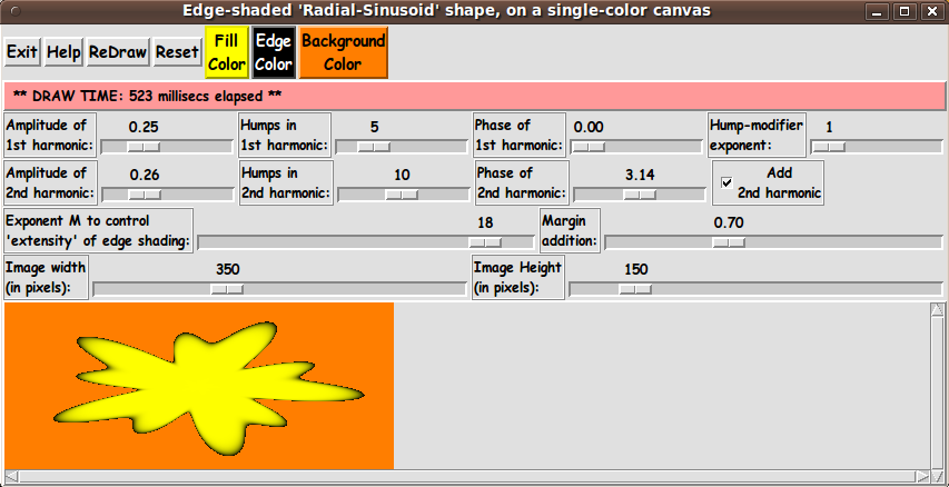
But one difference is that I can 'play' with the 'phase' angles --- a1 and a2 --- to get some different kinds of shapes from the rather symmetric 'super-formula' shapes.

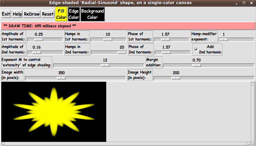
Also, I can 'play' with the 'number-of-humps' parameters --- n1 and n2 --- and the amplitude parameters --- A1 and A2 --- to get even more variety in the 'rippled-disk' shapes.

Here is a description of the 'color-shading-metric' that I devised for the super-formula shape.

It is a 'little-r-over-big-R' formula.

Let us say that x,y coordinates on the 'super-formula shape' outline --- and anywhere in the rectangular image area --- are measured from the center of the image area.

The distance from the origin to the point x,y is given by the Pythagorean formula:

r = sqrt( x^2 + y^2 )

Furthermore, our point x,y makes an angle 'theta', say with the x-axis.

I defined the 'color-shading-metric' for the super-formula shape to be

v = r(x,y) / R(theta)

where 'theta' is the angle whose sine is y/r --- and cosine is x/r. 'theta' can be determined by using the Tcl 'atan2' math function. atant2(y,x) returns the angle theta.

    (We have to treat the point where x=y=0 as a special case. We simply color that point with the 'fill' color for the shape.)

Note that 'little-r' is the distance to x,y.

And 'big-R' is the number given by the super-formula.

Note that for a point x,y in the interior of the 'super-formula shape', the ratio r/R is less than one --- because the point x,y lies on a radial line from 0,0 to the boundary of the 'super-formula shape', and the distance to that boundary is R(theta), which is greater than r.

Furthermore, the metric is zero at the origin (x,y)=(0,0), because r = sqrt( 0^2 + 0^2) = 0.

And, on the boundary of the 'super-formula shape', the values r and R are the same (because they are defined by the same point) --- so the metric is equal to 1.0.

And for x,y points outside the 'super-formula shape', v = r/R is greater than 1.0.

Thus we have a suitable 'color-shading-metric', v.


For the radial-sinusoidal shape, we use the same metric:

v = r(x,y) / R(theta)

The difference is in the formula that we use to compute R(theta).


Using the 'color-shading metric' to color a pixel
inside of (or outside of) the radial-sinusoid shape:

As we scan across the pixels of the rectangular image area, we can convert integer pixel coordinates (i,j) to 'real-number' 'world coordinates' (x,y) --- with (x,y) = (0.0,0.0) being somewhere in the middle of the rectangular image area.

At a point (x,y) inside the radial-sinusoid shape, the metric v is less than or equal to 1.0.

At a point (x,y) outside the radial-sinusoidal shape, the metric v is greater than 1.0.

For those external points, we simply set the color of the corresponding-pixel to the user-selected background color.

We determine the 'shaded color' at a point inside the radial-sinusoid shape by using a color interpolated between

  • the user-selected 'fill' color (color1) for the 'radial-sinusoid shape', and

  • the user-selected 'edge' color (color2).

We calculate the 'shaded color' at (x,y) by calculating a weighted average based on applying the factor (1.0 - v) to color1 --- and applying v to color2 (the 'edge' color).

That is:

shaded-color = (1 - v) * color1 + v * color2.

We actually calculate an RGB color via 3 equations like

shaded-R = (1 - v) * R1 + v * R2
shaded-G = (1 - v) * G1 + v * G2
shaded-B = (1 - v) * B1 + v * B2

Thus we will get the edge-shading (the 3D effect) for the 'radial-sinusoid shape'.

---

Actually, it turns out that 1-v and v gives a rather washed-out (too gradual) shading effect.

It is better if we raise v to a power M and use v^M and (1 - v^M).

It turns out that M = 12 gives pretty nice shading for the radial-sinusoid shape, but rather than hard-code the value of M, we provide a scale widget on the GUI so that the user can set the value of M.


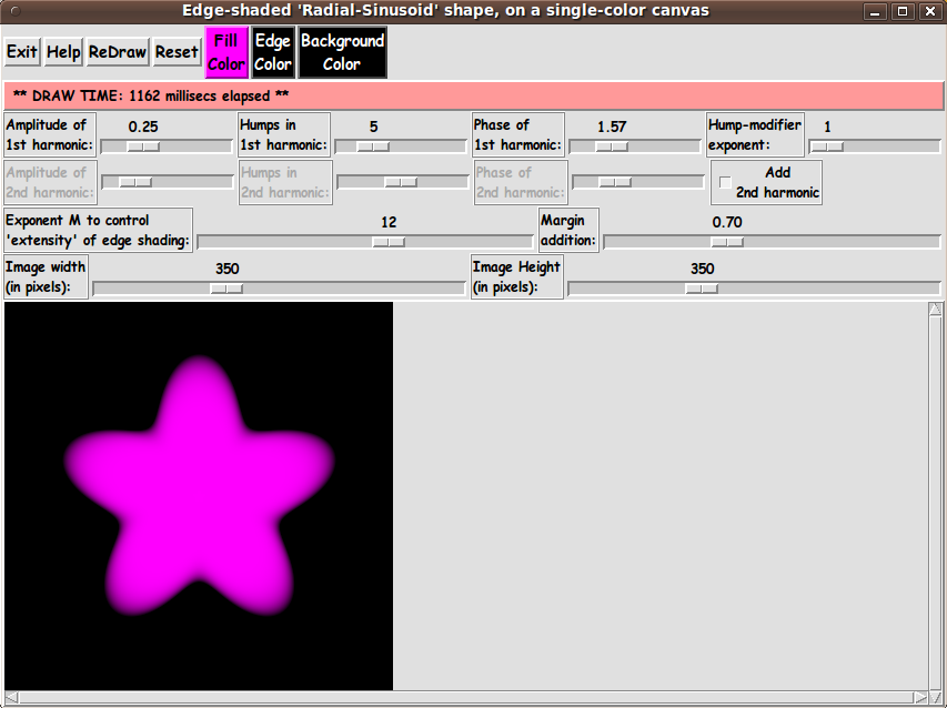
Assembling the pieces

Now it was a matter of putting the pieces together.

I took 'pieces' from some of my other Tk scripts that make color-shaded, 3D-like images.

I ended up with the following GUI --- which shows a 'radial-sinusoidal shape' with 5 'humps' --- as an initial display.

Note that I have supplied 3 buttons on the GUI with which to set the 'fill' color, the 'edge' color, and the 'background' color.

Those 3 buttons call on an 'external' color-selector-GUI script to set those colors.

You can make that color-selector script by cutting-and-pasting the code from the page that offers a non-obfuscated color selector GUI on this site.

    To get a nice color transition at the boundary of the shape, you may find that you may want to use the same color for the 'edge' and 'background' colors. That is the inital setting of this GUI.

---

Note that I supply an M-scale widget to the GUI to allow the user to control an exponent that is used to control 'extensity' --- the 'extent-and-intensity' of the shading at the border of the 'rippled-disk shape'.

I also added a display of 'elapsed time' for each redraw --- by using the Tcl 'clock milliseconds' command.

When I developed the script that I posted at wiki.tcl.tk and on this site, at GUI for Drawing 'Super-ellipses', with nice shaded edges, I learned my lesson about needing to use braces with 'expr' statements --- for much better execution times.

    (Brent Welch et. al. point this out before page 8 in the 4th edition of 'Practical Programming in Tcl and Tk' --- although they do not follow this advice in many 'expr' examples later in the book.)

It made a huge difference, so, in this script (and in all my Tk scripts henceforth), I consistently use braces with ALL 'expr' commands --- in particular, in the compute-intensive 'ReDraw' proc and in the procs that are called by 'ReDraw'.


DESCRIPTION OF THE CODE

Below, I provide the Tk script code for this 'color-gradient, radial-sinusoidal-shape' drawing utility.

I follow my usual 'canonical' structure for Tk code, for this Tk script:


  0) Set general window & widget parms (win-name, win-position,
     win-color-scheme, fonts, widget-geometry-parms, win-size-control).

  1a) Define ALL frames (and sub-frames, if any).
  1b) Pack   ALL frames and sub-frames.

  2) Define & pack all widgets in the frames, frame by frame.
              Within each frame, define ALL the widgets.
              Then pack the widgets.

  3) Define keyboard and mouse/touchpad/touch-sensitive-screen action
     BINDINGS, if needed.

  4) Define PROCS, if needed.

  5) Additional GUI initialization (typically with one or more of
     the procs), if needed.


This Tk coding structure is discussed in more detail on the page A Canonical Structure for Tk Code --- and variations.

This Tk coding structure makes it easy for me to find code sections --- while generating and testing this script, and when looking for code snippets to include in other scripts (code re-use).


Experimenting with the GUI

As in all my scripts that use the 'pack' geometry manager (which is all of my 100-plus Tk scripts, so far), I provide the four main pack parameters --- '-side', '-anchor', '-fill', and '-expand' --- on all the 'pack' commands for the frames and widgets.

I think I have found a good setting of the '-side', '-anchor', '-fill', and '-expand' parameters on the 'pack' commands for the various widgets of this GUI.

In particular ...

The 'canvas' widget expands/contracts appropriately when the window size is changed --- and button and label widgets stay fixed in size and relative-location as the window size is changed.

If anyone wants to change the way the GUI configures itself as the main window size is changed, they can experiment with the '-side', '-anchor', '-fill', and '-expand' parameters on the 'pack' commands for the various widgets --- to get the widget behavior that they want.

---

Additional experimentation:
You could change the fonts used for the various GUI widgets. For example, you could change '-weight' from 'bold' to 'normal' --- or '-slant' from 'roman' to 'italic'. Or change font families.

In fact, you may NEED to change the font families, because the families I used may not be available on your computer --- and the default font that the 'wish' interpreter chooses may not be very pleasing.

Furthermore, there are variables used to set geometry parameters of widgets --- parameters such as border-widths and padding. And you could change the '-relief' values for frames and widgets. Feel free to experiment with those 'appearance' parameters as well.


Some features of the code

There are plenty of comments in the code to describe what most of the code-sections are doing.

The most complex code is in the 'ReDraw' proc.

See the comments in that proc to see how it is implemented.

See the top of the 'PROCS' section for a list of the procs used in this Tk script.

See comments in the procs for details on the purpose of each proc and for details on the methods by which each proc was implemented.

Here is a quick overview of the procs --- to give an idea of the 'guts' of this utility:


 ReDraw                     - called by the 'ReDraw' button and in the 
                              'Additional GUI Initialization' section at the
                              bottom of this script.

                              Draws the radial-sinusoidal shape on the canvas for
                              the current scale parameter values and for the
                              current color var values.
  
 setMappingVars_for_px2wc   - called by the 'ReDraw' proc
  
 Xpx2wc                     - called by the 'ReDraw' proc
 
 Ypx2wc                     - called by the 'ReDraw' proc

 set_scale_Ymax_equal_Xmax  - called by a button1-release binding on the
                              X-imgsize scale widget

 set_shape_color1           - called by the 'fill' color button
 set_shape_color2           - called by the 'edge' color button
 set_background_color       - called by the 'background' color button
 update_color_button        - called by the 'set_*_color*' procs

 advise_user                - called by the 'ReDraw' proc and various bindings
  
 enable_disable_harmonic_widgets - called by a button1-release binding on the
                                   'Add harmonic' checkbutton

 reset_scales               - called by the 'Reset' button and in the
                              'Additional GUI Initialization' section at the
                              bottom of this script.

 popup_msgVarWithScroll     - called by the 'Help' button 


One thing that I discovered in testing this GUI is a 'trick' to make the GUI (in particular the 'canvas' area) resize nicely after a change to the image-size via the x and y image-size scale widgets.

It turned out that the resizing would not occur after the tester (me) would resize the window by tugging on an edge or corner of the window. The resizing would occur nicely before that 'manual intervention' with the window manager.

It turned out that a Tk 'wm' (window manager) command --- namely

wm geometry . {}

can be used to restore the nice auto-resizing of the canvas area around the image area.

By some searches on wiki.tcl.tk (with terms like 'wm resize'), I found this 'trick' used on the page http://wiki.tcl.tk/10720 (weeEdit) --- in the '-command' of a 'Resize window' button.

In that code, the 'wm geometry . {}' statment was being used to resize a 'text' widget, not a 'canvas' widget.

A search on 'wm geometry . {}' at wiki.tcltk revealed that this 'wm statement' was mentioned in a section titled 'word Wrap Via Tk Text Widget' --- on the page http://wiki.tcl.tk/44 (Additional string functions) --- with the comment 'Make sure the toplevel shrinks or expands to fit'.

Thanks to 'D.McC' (David McClamrock) for revealing this technique to me.

I have never seen this 'toplevel shrink/expand' technique --- using 'wm geometry . {}' --- mentioned in the Tcl-Tk books that I have used the most --- the Eric Foster-Johnson books and the Brent Welch books.

But I did find mention of this capability in the original 1994 edition of the John Ousterhout Tcl-Tk book --- on page 237 --- where it says:

    "If you would like to restore a window to its natural size, you can invoke 'wm geometry' with an empty geometry string:

    wm geometry . {}

    "This causes Tk to forget any size specified by the user or by 'wm geometry' so the window returns to its natural size."

Apparently 'wm geometry . {}' can be used to cause Tk to signal the window manager to resize the toplevel window according to the widget sizes within the window --- for example, after a user has 'manually' resized the toplevel window by 'tugging' on a window edge or corner.


Comments in the Code

It is my hope that the copious comments in the code might help Tcl-Tk coding 'newbies' get started in making GUI's like this.

Without the comments --- especially in the 'ReDraw' proc --- the code might look even more cryptic than it already is.

Without the comments, potential young Tcler's might be tempted to return to their iPhones and iPads and iPods --- to watch videos of dorm-room pranksters at work.


The Tcl-Tk Script CODE

Here is a link to CODE for the Tk script
'make_RadialSinusoidShape_2colorGradient_shadedEdges.tk'.

With your web browser, you can 'right-click' on this link --- and in the menu that pops up, select an item like 'Save Link Target As ...' --- to save this file to your local computer.

Then you can rename the file to remove the '.txt' suffix. Make sure that you have execute permission set on the file --- in order to execute the script.


MORE SCREENSHOTS

Here is a screenshot of the GUI after changing the 'fill' color from magenta to yellow.

Also, the 'humps' request was changed from 5 to 10 --- and the 'Add 2nd harmonic' checkbutton was turned on.

In addition, to show how a 'stretched' image can be achieved --- the ImageHeight scale widget was changed to a value different from the ImageWidth value.

The following image shows how an image may look when you make the 'background' color different from the 'edge' color.

Also this is an example of experimenting with the phase angles of the 2 harmonics.

In the images above, the shapes were like flowers with symmetric petals.

By using various phase angles, we can 'skew' the 'petals'/'humps'.

Control of the edge shading

On the subject of trying to get 'crisp' shading at the border of the 'radial-sinusoidal shape':

I put the M-scale widget on the GUI to adjust a 'pow' (power) function exponent to change the 'extensity' (extent-and-intensity) of the shading at the edge of the 'radial-sinusoidal shape'.

You will find that low powers (like 1 or 4 or even 6) give a rather 'washed-out' border to the shape.

It takes a rather high value (like 12) to get a good-looking edge.

That means that v^12 and (1 - v^12) gives a better-looking border when blending 'fill' color at a point x,y with the 'edge' color --- better than using the weighted average of the 2 colors using v and (1-v).


Drawing times

The display of the elapsed time for the draw is seen in a message line near the top of the GUI.

I found that with any parameter combinations (widget settings) that I tried, with an image size request of 350x350 pixels, the draw times were pretty consistently around 1.1 seconds.

And when I increased the image size to 800x800 pixels, the draw times were about 5.5 seconds.

For an image size of 100x100 pixels, the draw times are about 0.1 second on my medium-powered desktop computer.

So, in a quite reasonable amount of time, with this utility, you can get some nice high-quality images --- to use for 'bullets', icon-backgrounds, logo-backgrounds, and 'buttons'.

And I have the option of enhancing the Tk script on this page, to provide a few more capabilities to this 'button' generator --- including some changes to reduce draw times.

That is a really great thing about Tk scripts.

You have the code, hence you can change the utility to do what you want or need.


Some possible FUTURE ENHANCEMENTS

During the development of this script, I added most of the enhancements that I had on a 'to do' list for some of my other 'color-shaded, 3D-like' image-maker Tk scripts.

If I were to make changes to this script, I would most likely change the formula for R(theta) somewhat --- and then change the GUI accordingly.

I also might change the ranges of some of the scale widgets.

One other thing I might try is to scan the code in the 'ReDraw' proc looking for ways I could reduce the draw times.

I am not sure that I can reduce the draw times significantly.

I am already saving up all the hex-colors for an entire image (in a list of horizontal scan-line lists --- a list of lists).

I apply all of the pixel-colors to the image 'structure' in one 'put' call.

That is probably the most efficient way to build the image.

However, I could reduce the number of multiplications being performed (somewhat) --- and maybe achieve some speedup by using integer arithmetic rather than floating-point aritmetic in some operations.


IN CONCLUSION

As I have said on several other code-donation pages on this freedomenv.com site and on the Tclers' wiki at wiki.tcl.tk ...

There's a lot to like about a utility that is 'free freedom' --- that is, no-cost and open-source so that you can modify/enhance/fix it without having to wait for someone else to do it for you (which may be never).

A BIG THANK YOU to Ousterhout for starting Tcl-Tk, and a BIG THANK YOU to the Tcl-Tk developers and maintainers who have kept the simply MAH-velous 'wish' interpreter going.

Bottom of this page with
Tcl-Tk Code for a GUI to Draw a
RADIAL-SINUSOID-SHAPE
with color-shaded 3D-edges

--- a utility in the FE 'tkGooies' system,
in the 'IMAGEcreatorsShaded3D' group.

To return to a previously visited web page location, click on the Back button of your web browser a sufficient number of times. OR, use the History-list option of your web browser.
OR ...

< Go to Top of Page, above. >

Page history:

This FE web page was created 2016 Jan 10.

Page was changed 2016 Jan 11.
(Added another example screenshot.)

Page was changed 2019 Mar 01.
(Added css and javascript to try to handle text-size for smartphones, esp. in portrait orientation.)

Page was changed 2019 Jun 14.
(Specified image widths in percents to size the images according to width of the browser window.)


NOTE:
This code may someday be posted in a page on the Tcler's Wiki --- wiki.tcl-lang.org --- formerly wiki.tcl.tk. If I do that, I may put a link to the page here.