FE 'tkGooies' Utilities

'MATHed' subgroup of
the 'MATHtools' group

Tcl-Tk script
'tkCircleCircumference ByPolygons'

(Code for a GUI to
QUICKLY calculate
upper and lower
bounds on PI ---
the ratio of circle
circumference
to circle diameter)
(FE = Freedom Environment)

GUI interface to
approximate
the value of PI
with polygons
inscribing and
cirumscribing
a circle ---
like Archimedes did.

Large, hi-res images are below.

FE Home Page > FE Downloads Page >

FE 'tkGooies' Description Page >

FE 'tkGooies' 'MATHtools' Menu >

FE 'tkGooies' 'MATHed' Menu >

This
'tkCircleCircumferenceByPolygons'
tkGooie Code Page

INTRODUCTION to Tcl-Tk script
a 'tkCircleCircumferenceByPolgons'

For several years now (circa 2013-2015), I have been planning to make a Tk GUI that draws a circle and draws 'regular' polygons (inscribed within and circumscribed about the circle)
---
with the added capability to compute the circumferences of the polygons
---
as an approximation to the circumference of the circle.

The GUI could then easily show the ratio of the circumferences of the polygons to the diameter of the circle --- thus giving upper and lower bounds on the value of pi --- which is the ratio of the circumference of a circle to its diameter.

I was motivated to do this by seeing images like the ones in math books that describe (more or less vaguely) how Archimedes developed his often-mentioned lower and upper bounds for pi:

  • 3 and 10 / 71   =
    223 / 71
    ( ~ 3.14084507)

    and

  • 3 and 1 / 7   =
    3 and 10 / 70   =
    22 / 7
    ( ~ 3.142857143 )

accurate to about 3 decimal places (2.5?).


The book

'Geometry from Euclid to Knots',

by Saul Stahl (2003), pages 159-162, has a clear discussion of the 2 sequences of numbers (nested square roots involving the integers 2 and 3) that Archimedes used to estimate the lower and upper bounds for pi.

Stahl stops short of giving Archimedes' full argument.

Stahl says "Using some complicated methods for the estimation of square roots by means of fractions", Archimedes arrived at the 2 bounds above.

    Note that Archimedes used approximations to the square roots of 2 and 3 to get approximations to the value of pi. Approximations can beget approximations.

If I find some references that delineate those Achimedean methods, I plan to add link(s) to such descriptions here.

In the mean time, you can use this WEB SEARCH on keywords

archimedes pi circle polygons circumference square roots

to look for information on how Archimedes approximated the square roots.

    (NOTE:
    This geometry book by Stahl is quite unusual in that the first chapter starts out with a description of 'spherical geometry' and 'hyperbolic geometry' before going on to Euclidean 'plane geometry'.

    Furthermore, Stahl devotes the 2nd chapter to deriving results in 'plane geometry' that do not require use of the 'parallel postulate'.

    The 3rd chapter invokes the parallel postulate.)


If you want more information on the subject of calculation of approximations to pi, you can see Wikipedia pages on

And if you want more information on Archimedes and methods of calculating pi via polygons, you can do a WEB SEARCH on keywords like


NOTE:
We are not 'trigonometrically cheating' with this 'app'.

Because we are using a computer and sine and cosine routines, it may seem like cheating compared to what Archimedes did, circa 287 to 212 BCE, using square roots. BUT ...

This Tk script essentially mimics the fact that back in the time of

those ancient mathematicians could have computed the circumferences of these polygons to much better accuracy than Archimedes achieved --- by using their trigonometry tables instead of using square-roots, like Archimedes did.

With this Tk script, we are speeding up (by a factor of many thousands) the computations that mathematicians could perform many hundreds of years ago.


Basic Goals of the Tk Script:

My purpose for this Tk GUI script is/was to generate a circle and 2 polygons in a square image area on the GUI.

The drawings are to be done in a square image area on a Tk 'canvas' widget in a Tk 'frame' widget.

The GUI is to provide widgets by which the user could specify the important variables for drawing the circle and polygons:

  • number of sides for a given drawing of the 'inner' and 'outer' polygons

  • size of the square image area (in pixels)

  • a radius for the circle (in 'world coordinate units')

Rather than using the common simplifying technique of using a circle of 'unit radius', this GUI is to allow the user to specify radii in a wide range --- say, 0.1 to 300.0.

    I can remember back to my first geometry and algebra classes (when about 12 to 14 years old) wondering how can people be so sure that the ratio of the circle circumference to its diameter is the same no matter what the size (radius) of the circle.

    I was not told of the trick of imagining standing back from the circle at various distances --- and the marks of a diameter around the circumference of the circle (arcs the length of the diameter) would not appear to change in their relative location.

    Even if I had known that, I probably would not have felt that that was a 'rigorous proof'.

    It was more like a 'confirmation of plausibility'.


PLANNED LAYOUT OF THE GUI:

As I have done with other Tk scripts that I have written in the past year or so, I laid out a 'text image' of the GUI --- to aid me as I coded the frames and widgets.

I used the following conventions to make the sketch, with a text editor.


  SQUARE-BRACKETS indicate a comment (not to be placed on the GUI).
  BRACES          indicate a Tk 'button' widget.
  A COLON         indicates that the text before the colon is on a 'label' widget.
  <---O--->       indicates a Tk 'scale' widget.
  CAPITAL-X       indicates a Tk 'checkbutton' widget.
  CAPITAL-O       indicates a Tk 'radiobutton' widget (if any).
  UNDERSCORES     indicate a Tk 'entry' widget (if any).


According to those conventions,
I created the following 'text sketch'.


 FrameNames
 VVVVVVVVVV
              -----------------------------------------------------------------------------
              tkCircleCircumferenceByPolygons
              [window title]
              -----------------------------------------------------------------------------

 .fRbuttons   {Exit} {Help} {ReDraw} {Backgd  {Circle  {Inscribed     {Circumscribed
                                     Color}   Color}   Polygon Color} Polygon Color}

                                           50      3000
 .fRcontrols1 Image width&height (pixels): <-----O----> Polygon to draw:  X Inner  X Outer

                               3          360            0.1            300.0     
 .fRcontrols2 Number of sides: <------O----->    Radius: <--------O--------->
 
 .fRmsg       [ .......... Message line --- Calculated Circumferences are shown here .... ]

 .fRcanvas    -----------------------------------------------------------------------------
              |                                                                           A
              |                                                                           |
              |                                                                           |
              |  'Canvas' for displaying the circle and polygons                          |
              |   in a square image area.                                                 |
              |                                                                           |
              |                                                                           |
              |                                                                           |
              |                                                                           V
              <-------------------------------------------------------------------------->


Perhaps some aspects of the sketch could use a little more explanation:


  A LINE (HYPHENS or VERTICAL-BARS) WITH AN 'ARROW-HEAD' AT EACH END indicates
  a Tk 'scale' widget --- or a 'scrollbar' widget.

  A combination of VERTICAL-BAR CHARACTERS AND HYPHEN (or UNDERSCORE) CHARACTERS,
  that outline a RECTANGULAR SHAPE, are used to indicate either a Tk 'canvas' or
  a Tk 'listbox' widget or a Tk 'text' widget.

  SCROLL-BAR 'ARROW-HEADS' (for a 'canvas', 'listbox', or 'text' Tk widget)
  are drawn as follows:

   UP    ARROW-HEAD   is drawn with a CAPITAL-A.
   DOWN  ARROW-HEAD   is drawn with a CAPITAL-V.
   LEFT  ARROW-HEAD   is drawn with a LESS-THAN sign.
   RIGHT ARROW-HEAD   is drawn with a GREATER-THAN sign.

  UP-and-DOWN    ARROW-HEADS  at the right/left of a box shape indicate
  a VERTICAL SCROLL-BAR there.

  LEFT-and-RIGHT ARROW-HEADS  at the bottom/top of a box shape indicate
  a HORIZONTAL SCROLL-BAR there.

  The arrow-heads on a horizontal scrollbar are joined by hyphens, rather than
  underscores.


From the diagram above, I could see that this GUI will contain about:

  • 7 'button' widgets
  • 4 'label' widgets
  • 3 'scale' widgets
  • 1 'canvas' widget (with x-y scrollbars)
  • 2 'checkbutton' widgets
  • 0 'radiobutton' widgets
  • 0 'entry' widgets
  • 0 'listbox' widgets
  • 0 'text' widgets

Assembling the pieces   (The GUI)

Now it was a matter of putting the pieces together. I took 'code-pieces' from some of my other Tk scripts that 'draw' in an image area on a Tk canvas.

I ended up with the following GUI as an initial display.

Note that I have provided 4 color buttons on the GUI so that the user can control

  • the background color of the image area
  • the color of the circle outline
  • the color of the 'inner' polygon outline
  • the color of the 'outer' polygon outline

I also provided several 'scale' widgets by which to control

  • the size of the square image area (in pixels)

  • the number of sides to use in drawing the 'inner' and 'outer' regular polygons

  • a radius for the circle (in 'world coordinate units', not pixels)

I also provided a couple of 'checkbutton' widgets on the GUI by which the user can choose to draw the 'inner polygon', the 'outer polygon', both, or neither.

By default, the GUI starts with both polygons drawn over the circle --- and with hexagons for the two polygons.

A message area in the middle of the GUI displays calculation results:

  • circumference of the 'inner' polygon (in 'world units')

  • circumference of the 'outer' polygon (in 'world units')

  • ratio of these 2 circumferences to the diameter of the circle
    (which is twice the radius specified by the user)

  • the difference of the two ratios from the 'true' value of pi

---

Below is an image drawn after changing NumSides to 96 (like what Archimedes used) and increasing the size of the image area to 450 x 450 pixels --- and after changing the radius from 50.0 to 137.7.

Before capturing this image, I changed the 'format' statements in the script that determine the number of decimal digits to display.

Since I had room in the results-message area, I changed from 6 digits to 8 digits.

    (You can change a 'decimalDIGITS' variable at the bottom of the script if you want to change this.)

Execution time:

The drawing and computations complete almost immediately after clicking on the 'ReDraw' button --- even if you request hundreds of sides for the two polygons.

Wouldn't Archimedes (and Galileo and Newton and Euler and the Bernoulli's and Gauss and Lagrange and Laplace and Weierstrass and Poincare and Riemann and ...) have loved to be able to use Tcl-Tk?

I wonder what wonders Archimedes would have performed with the 'wish' interpreter at his disposal?

Sure beats drawing in the sand.
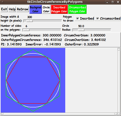
Changing the Radius
(to confirm that pi is a constant, independent of circle size)

The user can change the radius 'scale' widget repeatedly (and click on the 'ReDraw' button after each change) to see that the two ratios (polygon circumference to diameter) do not change.

    Of course, this could be predicted by careful examination of algebraic formulas that summarize how the calculations are performed.

    A radius factor in the numerator and denominator cancel out.

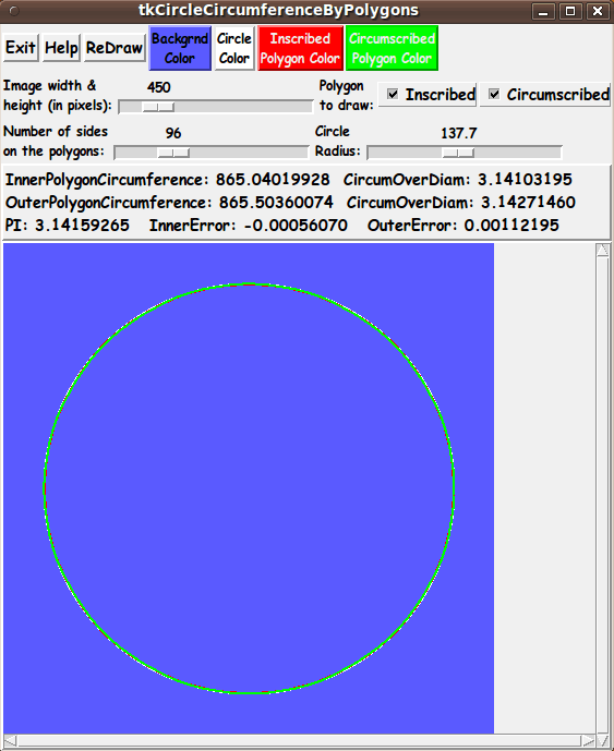
Increasing the Number of Sides
(a lot)

The results we see with this tool suggest that we can 'squeeze down' to a unique number --- called pi.

    (By examining the algebraic formulas for the two polygon circumferences, it should be provable that the difference between the two polygon circumferences goes to zero --- and one is bounded above and always increasing, while the other is bounded below and always decreasing. So each sequence goes to a unique limit --- the same limit.)

Other changes to try:
(to push the accuracy of the ratios
to many decimal digits)

You can change the NumSides to 360, so that the central angle of each sector of the polygons is exactly one degree.

These polygons are almost indistinguishable from the circle. You will see that the errors are out at the 6th decimal digit.

Five decimal digits is more than enough accuracy for most engineering work.

A couple of quotes from a 2009 document 'Computing the Digits in Pi' by Carl Offner (University of Massachusetts, Boston):

    "I asked a civil engineer how many digits of pi he would actually ever need. After thinking about it for a while, he agreed with me that 5 was probably pushing it."

    "It requires ... 39 digits of pi in order to compute the circumference of a circle of radius 2 × 10 to the 25th meters (an upper bound on the distance traveled by a particle moving at the speed of light for 20 billion years, and as such an upper bound on the radius of the universe) with an error of less than 10 to the -12 meters (a lower bound for the radius of a hydrogen atom)."

    Borwein and Borwein (1984)

    "But what do astronomers and astrophysicists really need?

    I spoke to two recently. One had used whatever the pi key on her calculator produced -- at most, 10 digits.

    The other thought that 7 or 8 places was the most he'd ever seen the need for.

    And even in quantum field theory, where there are physical constants that are known to an astounding accuracy of 12 or 13 decimal places, it wouldn't really help to know pi to any greater accuracy than that."

    A computer engineering viewpoint:

    "In recent years, the computation of the expansion of pi has assumed the role as a standard test of computer integrity. If even one error occurs in the computation, then the result will almost certainly be completely in error after an initial correct section. On the other hand, if the result of the computation of pi to even 100,000 decimal places is correct, then the computer has performed billions of operations without error. For this reason, programs that compute the decimal expansion of pi are frequently used by both manufacturers and purchasers of new computer equipment to certify system reliability."

    Bailey (1988)


Scrollable Canvas
(and big image area)

Note that the canvas in the GUI has vertical and horizontal scrollbars --- and you can set a large image area size with the image-size scale widget.

So you can set a very large image area in which to do the drawings.

And if you think the max-pixels of the image-size scale widget is not big enough for you, you can edit the Tk script and change the '-to' parameter on the 'scale' widget for the image size.

Distance units

You can think of the radius being specified in whatever units you want --- feet, yards, meters, kilometers.

Hence you can imagine drawing a huge circle on a big flat beach or a flat river delta --- a circle with a radius of 100 meters or more.

You pound a stake in the ground and attach a rope that is 100 meters long.

Then you use the other end of the rope to 'scribe' a big circle on the beach.

Then you see how many times you can measure off the rope distance (the radius) on that scribed circle.

It should be two-pi times ( 6.28... ) --- 6 rope lengths plus a little more than a quarter of the rope.

---

Implementing the Color Buttons

The 2 color buttons call on an 'external' color-selector-GUI script to set those colors.

You can make that color-selector script by cutting-and-pasting the code from the page that offers

a non-obfuscated color selector GUI

on this site.

You can see the code at the bottom of the Tk script to see how the name and location of the color selector script is set.


DESCRIPTION OF THE CODE

Below, I provide the Tk script code for this 'tkCircleCircumferencesByPolygons' 'app'.

I follow my usual 'canonical' structure for Tk code, for this Tk script:


  0) Set general window & widget parms (win-name, win-position,
     win-color-scheme, fonts, widget-geometry-parms, win-size-control).

  1a) Define ALL frames (and sub-frames, if any).
  1b) Pack   ALL frames and sub-frames.

  2) Define & pack all widgets in the frames, frame by frame.
              Within each frame, define ALL the widgets.
              Then pack the widgets.

  3) Define keyboard and mouse/touchpad/touch-sensitive-screen action
     BINDINGS, if needed.

  4) Define PROCS, if needed.

  5) Additional GUI initialization (typically with one or more of
     the procs), if needed.


This Tk coding structure is discussed in more detail on the page A Canonical Structure for Tk Code --- and variations.

This Tk coding structure makes it easy for me to find code sections --- while generating and testing this script, and when looking for code snippets to include in other scripts (code re-use).


Experimenting with the GUI

As in all my scripts that use the 'pack' geometry manager (which is all of my 100-plus Tk scripts, so far), I provide the four main 'pack' parameters:

  • '-side'
  • '-anchor'
  • '-fill'
  • '-expand'

on all the 'pack' commands for the frames and widgets.

I think I have found a good setting of the '-side', '-anchor', '-fill', and '-expand' parameters on the 'pack' commands for the various widgets of this GUI.

In particular ...

The 'canvas' widget will expand/contract appropriately when an image size 'scale' widget value is changed --- and
button and label and scale widgets stay fixed in size and relative-location as the window size is changed.

If anyone wants to change the way the GUI configures itself as the main window size is changed, they can experiment with the '-side', '-anchor', '-fill', and '-expand' parameters on the 'pack' commands for the various widgets --- to get the widget behavior that they want.

---

Additional experimentation with
the appearance of the GUI:

You could change the fonts used for the various GUI widgets.

For example, you could change '-weight' from 'bold' to 'normal' --- or '-slant' from 'roman' to 'italic'.

Or change font families.

    In fact, you may NEED to change the font families, because the families I used may not be available on your computer --- and the default font that the 'wish' interpreter chooses may not be very pleasing.

Furthermore, there are variables used to set geometry parameters of widgets --- parameters such as border-widths and padding.

And you could change the '-relief' values for frames and widgets.

Feel free to experiment with those 'appearance' parameters as well.


Some features of the code

There are plenty of comments in the code to describe what most of the code-sections are doing.

The code 'comes together' in the 'Redraw' proc.

See the comments in that proc to see how it is implemented.

See the top of the 'PROCS' section for a list of the procs used in this Tk script.

See comments in the procs for details on the purpose of each proc and for details on the methods by which each proc was implemented.

Below is a quick overview of the procs --- to give an idea of the 'guts' of this utility:


  - setMappingVars_for_px2wc        - called by the 'set_MappingVars_forImageSquare'
                                      proc below.

  - set_MappingVars_forImageSquare  - called by the 'draw_*' procs below.

  - Xwc2px                          - called by the 'draw_*' procs below.
  - Ywc2px                          - called by the 'draw_*' procs below.

  - draw_circle               - called by the 'Redraw' proc below.

  - draw_inner_polygon        - called by the 'Redraw' proc below.

  - draw_outer_polygon        - called by the 'Redraw' proc below.

  - Redraw                    - called by the 'ReDraw' button.

  - set_bkgd_color            - called by the background-color button '-command'

  - set_circle_color          - called by the circle-color button '-command'

  - set_inscribed_color       - called by the inner-polygon-color button '-command'

  - set_circumscribed_color   - called by the outer-polygon-color button '-command'

  - update_button_colors      - called by the 'set_*_color' procs and once
                                in the 'Additional GUI Initialization section.

  - advise_user               - called by the 'Redraw' proc
 
  - popup_msgVarWithScroll    - called by 'Help' button


A 'resizing-the-GUI' trick

One thing that I discovered in testing a previously-created GUI is a 'trick' to make the GUI (in particular the 'canvas' area) resize nicely after a change to the image-size via the image-size scale widget.

It turned out that the resizing would not occur after the tester (me) would resize the window by tugging on an edge or corner of the window.

The resizing would occur nicely before that 'manual intervention' with the window manager.

It turned out that a Tk 'wm' (window manager) command --- namely

wm geometry . {}

can be used to restore the nice auto-resizing of the canvas area around the image area.

By some searches on the Tclers' Wiki at wiki.tcl.tk (with terms like 'wm resize'), I found this 'trick' used on the page http://wiki.tcl.tk/10720 (weeEdit) --- in the '-command' of a 'Resize window' button.

In this code, the 'wm geometry . {}' statment was being used to resize a Tk 'text' widget, not a 'canvas' widget.

A search on 'wm geometry . {}' at wiki.tcl.tk revealed that this 'wm statement' was mentioned in a section titled 'word Wrap Via Tk Text Widget' --- on the page http://wiki.tcl.tk/44 (Additional string functions) --- with the comment 'Make sure the toplevel shrinks or expands to fit'.

Thanks to 'D.McC' (David McClamrock) for revealing this technique to me.

I have never seen this 'toplevel shrink/expand' technique --- using 'wm geometry . {}' --- mentioned in the Tcl-Tk books that I have used the most --- the Eric Foster-Johnson books and the Brent Welch books.

But I did find mention of this capability in the original 1994 edition of the John Ousterhout Tcl-Tk book --- on page 237 --- where it says:

    "If you would like to restore a window to its natural size, you can invoke 'wm geometry' with an empty geometry string:

    wm geometry . {}

    "This causes Tk to forget any size specified by the user or by 'wm geometry' so the window returns to its natural size."

Apparently 'wm geometry . {}' can be used to trigger a signal to the 'wish' interpreter and/or the window manager to resize the toplevel window according to the widget sizes within the window --- for example, after a user has 'manually' resized the toplevel window by 'tugging' on a window edge or corner.


To potential Tcler's
(on comments in the code)
(and to people who care about this planet)

It is my hope that the copious comments in the code might help Tcl-Tk coding 'newbies' get started in making GUI's like this.

Without the comments --- especially in the 'draw_*' procs --- the code might look even more cryptic than it already is.

Without the comments, potential young Tcler's might be tempted to return to their iPhones and iPads and iPods --- to look for

  • videos of Greenland's (and New Zealand's and Argentina's and Canada's and Alaska's and ...) glaciers melting

    and

  • time-lapse images of polar ice receding

    and

  • people reporting on receding caps on snow-capped mountains where they have lived for more than 50 years

    and

  • penguin colonies residing on mud where there used to be snow and ice

    and

  • beached walruses

    and

  • increasing evidence of drowning polar bears

    and

  • people on Pacific and Indian Ocean islands up to their ankles in water (unlike when they were kids)

    and

  • so on.

      while Republicans like Ted Cruz and Newt Gingrich and George Bush and Marco Rubio and Sarah Palin and various lobbyists and hundreds (and thousands) of others deny that anything is different from back in the 1960's when they were growing up.

      Wake up, people. There are many, many thousands more

      • petroleum gas flares

      • steam heaters to drive turbines

      • metal furnaces

      • manufacturing ovens (paint drying, curing, etc.)

      • kilns (for ceramics, concrete, etc.)

      • car engines

      • plane engines

      • ship engines

      • home furnaces

      • people (energy-consumers, forest-burners, etc.)

      than there were in the 1950's and 1960's.

        (Just watch a few episodes of the TV show "How It's Made".

        There is an oven or foundry in almost every show.

        Most of those did not exist in the 1950's.)

      The more-than-600 intensely burning oil wells in Kuwait, that burned for almost a year, in 1991, did not help.

      But, even worse, the gas flares from current oil exploration sites go on and on and on and on --- 24/7.

      I remember when they were all over south Texas when I was growing up in the 1950's.

      And they still go on in Texas --- and South Dakota and other states --- and areas around the world.

      The people who point to the occasional blizzard in the past few years as evidence against global warming are taking a very myopic view of the climate picture.

      Global warming started showing symptoms about 60 years ago (around 1940 to 1970 --- approximately 1955, to pick a year).

      Those symptoms have just now (around 2015) started getting clear enough to be undeniable to anyone who really looks around and exposes themselves to what is happening in many tell-tale parts of the Earth.

      Note that humans are burning up the fossil fuels (coal and petroleum) that have been stored underground for millions of years in the space of about 200 years.

      That's millions of years of solar energy stored in organic matter.

      Doesn't this fact alone give you an inkling of what is going on?

      It's not birds, fish, non-human mammals, insects, bacteria, viruses, or plants that are putting huge amounts of heat energy into the Earth's atmosphere

      Of all the living, reproducing things on Earth, it is only humans who are generating massive amounts of heat from potential energy that was generated thanks to the sun and stored underground over millions of years.

      Cows are not building coal fired power plants and drilling wells and flaring off the gas.

      Cows are not building air conditioners and gas furnaces.

      Cows are not living in air conditioned comfort --- unless the humans who eat them choose to condition the cows' air.

      Perhaps all this heat accumulation is 'boiling off' the lighter gases of our atmosphere --- oxygen before carbon dioxide --- into outer space.

      Perhaps this is a factor in rising carbon dioxide levels.

      I have not seen any mention of scientists investigating this possibility, but it certainly seems plausible --- and seems like a question that needs an answer.

      All these heat-generators are growing in direct proportion to the human population --- which is growing more than exponentially, as shown by plot images from two of the 'tkGooies' 'PLOTtools':

      Bye, bye, Greenland glaciers.

      Bye, bye, polar bears.

      Cruz and Gingrich and Trump and McConnell and Perry and about 100 million other Republicans do not give a damn about you and dear Mother Earth.

      They won't care about this planet until the rising water gets their socks wet (and their vacation-home living rooms wet) and when their air conditioners can't keep up with the heat or are too costly to run.

      Then they might look to some scientists and engineers and U.S. workers for help.

      Meanwhile, your tax dollars are being diverted into the pockets of their corporate buddies --- and eventually some of that finds its way into their pockets.

      Anyway, after you use your i-devices to look around at what is happening to our planet, and after you express some outrage to your congress-people over their head-in-the-sand attitudes and counter-productive votes, I urge you to try some Tcl-Tk coding --- to calm your nerves and take your mind off of a planet being degraded.


      The Tcl-Tk Script CODE

      Here is a link to CODE for the Tk script

      'tkCircleCircumferenceByPolygons.tk'.

      With your web browser, you can 'right-click' on this link --- and in the menu that pops up, select an option like

      ' Save Link Target As ... '

      to save this file to your local computer.

      Then you can rename the file to remove the '.txt' suffix.

      Make sure that you have execute permission set on the file --- in order to execute the script.

Some possible FUTURE ENHANCEMENTS

There are quite a few enhancements that could be considered for this script, such as:

  1. Provide an XY plot (and an animation?) of the Pi estimates

    Instead of requiring the user to specify a single N (number of sides) at a time and click on the 'ReDraw' button for each calculation, we could add an 'Animate' or 'Automate' button on the GUI to run through the calculations for N = 3 to 1000 sides, say.

    The current image area could be used to display the circle and polygons --- or, since the polygons would rapidly blend into the circle --- the image area could be used to plot 'inner-polygon-circumference-over-diameter' and 'outer-polygon-circumference-over-diameter' against N.

    The XY plot would show the two ratios 'squeezing down' at the level of 3.1415...

    A 'WritePlot' button could be added to the GUI to allow for quickly writing out the plot to an image file --- such as a Postscript file.

    Alternatively, if it were desirable to show the XY plot being drawn, point (pair) by point (pair), the GUI could offer an option to write an animated-GIF file (or movie file) from a sequence of images generated from the animated XY plot.

    It would certainly be more convenient than having to do a bunch of image captures and manually contruct an animated-GIF (or movie) file from a sequence of still-image captures.

    I have implemented a Write-Ani-GIF option in several 'tkGooies' in the 'IMAGEtools' group, such as:

    I can use code from one or more of those Tk scripts to make it relatively easy to implement a Write-Ani-GIF option --- although I might have to do some sort of Postscript to GIF conversion.

  2. Different (Polygon) Methods of Calculating Pi

    There are many different methods of calculating pi --- many are series expansions or integrals --- but some also depend on using polygons --- such as the Liu Hui algorithm (described on Wikipedia).

    The current script and GUI are complex enough that it probably would not be advisable to add any more algorithms to this script.

    However, this script could be used as a model for implementing some of the other geometry-oriented methods of computing pi.

  3. 3D geometry algorithms

    There might be some nice algorithms for computing pi based on 3D geometry constructs.

    If one were ambitious, one could probably show the 3D geometry in an image area on a Tk canvas --- similar to the way that 3D model files can be read and viewed with a 3D viewer utility, like the FE 'tkGooies' Tk script at

    A 3D Model Examiner that reads 3D model files.

The bottom line here is that there are almost always non-trivial enhancements (or 'forks') that could be made to (or from) a Tk GUI 'app' like this.

One advantage of this Tk script is that it is 'open' code --- available to anyone for enhancement.

So if you would like to take a different approach to approximating pi, you are welcome to take this code and build on it.


IN CONCLUSION

As I have said on other code-donation pages on this site ...

There's a lot to like about a utility that is 'free freedom' --- that is, no-cost and open-source so that you can modify/enhance/fix it without having to wait for someone else to do it for you (which may be never).

A BIG THANK YOU to Ousterhout for starting Tcl-Tk, and a BIG THANK YOU to the Tcl-Tk developers and maintainers who have kept the simply MAH-velous 'wish' interpreter going.

2016mar23 UPDATE --- RE-POSITIONING THE OUTER POLYGON

The image of the inner and outer polygons (in many math books and web pages on Archimedes) is typically shown with the outer-polygon 'sectors' rotated from the inner-polygon sectors (by half of the polygon-sectors' angle).

That is the configuration of the 2 polygons that was used in the initial Tk script implementation, as seen in the drawings in the images above.

However, this 'rotated' configuration does not show that the inner-polygon sectors fit exactly into the outer-polygon sectors.

Such a 'fitted' configuration would emphasize that, clearly, the lengths of the line-segments of the outer-polygon are longer than the line-segments of the inner polygon
---
and thus that the circumference of the outer-polygon is always bigger than the circumference of the inner-polygon, for a given number of sides N.

So I decided to add a 'checkbutton' widget to the top of the GUI, so that the user can draw the circle and 2 polygons with the 2 polygons aligned so that their corresponding sides are parallel.

See the checkbutton --- and the new drawing configuration --- in the following image.

This drawing configuration shows very convincingly that the circumference of the outer-polygon is always bigger than the circumference of the inner polygon, for any given N.

Furthermore, it makes it easier to show, mathematically, that the two circumferences converge to each other.

Let us compare the length of the segments of the inner and outer polygons when the sectors 'coincide'.

Let 'r' be the radius of the circle, and 'R' be the distance to the end-points of the sides of the outer-polygon, from the center of the circle.

Let N be the number of sides in the two polygons.

Let ANG = 2*pi/N be the interior angle of the sectors.

Let 'd' be the side-lengths of the inner-polygon.

Let 'D' be the side-lengths of the outer-polygon.

Then ...


   1) d = 2 * r * sin(ANG/2)
   
   2) D = 2 * R * sin(ANG/2)
   
   3) A diagram of an outer-polygon sector
      and the definition of the cosine gives us
      the relation:  r/R = cos(ANG/2)
      So R = r/cos(ANG/2)
   
   4) Equation-2 becomes D = 2 * r * sin(ANG/2)/cos(ANG/2)
                           = 2 * r * tan(ANG/2)
   
   5) Hence
      D - d = 2 * r * sin(ANG/2) * (1/cos(ANG/2) - 1)
   
      So (D - d) approaches zero as ANG goes to zero.
   
      Note that because BOTH of the 2 factors on the
      far right go to zero as ANG goes to zero, the
      difference (D - d) goes to zero 'quadratically'
      (really fast) as ANG goes to zero.


However, the question to be asked is:

Does the difference in the CIRCUMFERENCES of the 2 polygons go to zero as ANG goes to zero??

The difference in circumferences, 'C' and 'c', say, is


   C - c = N*D - N*d

         = N * (D - d)

         = N * 2 * r * sin(ANG/2) * (1/cos(ANG/2) - 1)

   where ANG = 2*pi/N.


Note that as N is increasing, the last two factors are decreasing to zero.

Some arguments using power series approximations to sin(ANG/2) show that sin(ANG/2) approaches ANG/2 as ANG goes to zero.

So the N factor in front cancels with the N in the denominator of ANG = 2*pi/N --- and we are left with some constants times (1/cos(ANG/2) - 1), which goes to zero as ANG goes to zero.

    (This argument can be expressed even more rigorously --- using the definitions and proof techniques that are used in math classes on limits of sequences of numbers.

    "For any given positive number 'epsilon', no matter how small, there exists an integer 'N', such that for all 'n' greater than 'N', etc. etc.")

So ... YES ... (C - c) does go to zero as ANG goes to zero --- and the two circumferences DO converge to the same number.

That is, the upper-limit of the little-c's and the lower-limit of the big-C's is the same number.

    We are using here 'boundedness' theorems from math of numeric sequences:

    • An increasing sequence that is bounded above converges to a finite limit.

    • A decreasing sequence that is bounded below converges to a finite limit.

    We just showed above, fairly rigorously, by algebraic and trigonometric means, that the 2 limits must be the same number.

    In contrast, if we kept calculating the circumferences for larger and larger N, we could become more and more convinced that the two circumferences are approaching each other very closely.

    But the possiblity exists that the differences could 'level out' toward some very small number greater than zero.

    The argument above indicates, quite convincingly, that that will not happen.

---

Note that whichever of the two 'rotated' positions you use for the outer polygon, all the results of computations for the circumferences and ratios and errors --- in the 'results' area of the GUI --- remain the same, for a given N.

And the results are the same, for a given N, no matter the radius we choose for the circle --- via the radius 'scale' widget on the GUI.


I have replaced the code at the CODE-link above with the code that provides the rotate-checkbutton.

Bottom of this web page for
presenting Tcl-Tk code for
'tkCircleCircumferenceByPolygons'
--- a 'tkGooie' script 'app'
in the FE 'tkGooies' system,
in the 'MATHed' subgroup of
the 'MATHtools' group.

To return to a previously visited web page location, click on the Back button of your web browser a sufficient number of times. OR, use the History-list option of your web browser.
OR ...

< Go to Top of Page, above. >

Page history:

This FE web page was created 2016 Mar 16.

Page was updated 2016 Mar 23.
(Added a 'rotate' checkbutton to the GUI.)

Page was updated 2016 Mar 28.
(Added some links.)

Page was changed 2019 Mar 05.
(Added css and javascript to try to handle text-size for smartphones, esp. in portrait orientation.)

Page was changed 2019 Jul 03.
(Specified image widths in percents to size the images according to width of the browser window. Also, added some web links.)


NOTE:
This code and description has not been posted on a Tcler's Wiki page --- at wiki.tcl-lang.org --- formerly wiki.tcl.tk.

If I ever do so, as a backup and alternative to this page, I plan to add a link to that page here.