FE 'tkGooie' Utilities

IMAGEcreators
Shaded3D group

A Tk GUI
to Draw an
N-sided POLYGON

with color-shaded,
3D-like edges

(FE = Freedom Environment)

FE 'tkGooie' interface for
a maker of color-shaded,
3D-like N-sided POLYGONS
---
on a potentially
different-colored
background.

FE Home Page > FE Downloads Page >

FE 'tkGooies' Description Page >

FE 'tkGooies' 'IMAGEcreatorsShaded3D' Page >

This 'draw_NsidedPOLYGON_colorShaded3D' tkGooie Page

INTRODUCTION to
Tcl-Tk Code for a GUI to
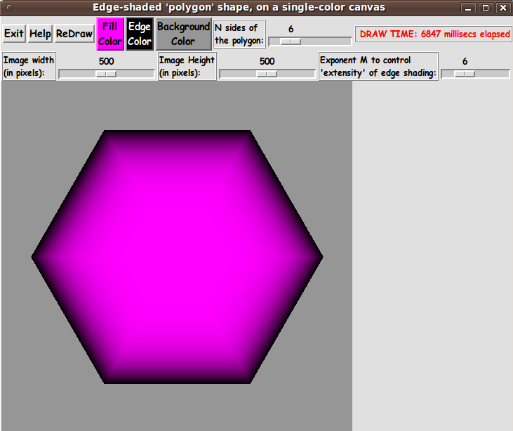
'Draw a N-sided-POLYGON
with color-shaded, 3D-like edges'

I am interested in making nice images for 'toolchest' and 'drawer' backgrounds (and other GUI embellishments), as I have indicated in pages at wiki.tcl.tk (and on this freedomenv.com site) --- such as

and

On the page that presents code for a GUI for Drawing 'Super-ellipses', with nice shaded edges on this site (and at wiki.tcl.tk), I presented code for a GUI that uses 'create image' on a canvas, along with 'put' commands, to implement the drawing of a 'super-ellipse' with nice 'edge shading' --- shading from a user-specified color for the super-ellipse to a user-specified color for a surrounding background.

(Thanks to 'ulis', deceased in 2008, for his donated script that led to that much-enhanced script. R.I.P.)

The edge-shading technique was based on using a 'color-metric' scalar parameter given by the equation for the super-ellipse:

v = |x/a|^n + |y/b|^n

I was able to use this 'color-metric' technique to create another Tk script that provides nice 'edge shading' for a rectangle with a color gradient across it (in the x or y direction).

A page on this site (and at wiki.tcl.tk) presents code for a GUI for Drawing Rectangular 'Buttons' with nice shaded edges. In that case, the color-metric that I used was of the form:

v = max(abs(x/xhalf), abs(y/yhalf))

where x and y are measured from an 'origin' in the middle of the rectangle, and xhalf and yhalf represent the half-width and half-height of the rectangle.

In both the color-gradient-super-ellipse case and the color-gradient-rectangle case, I transformed a script based on a Tk canvas-'create line' technique --- like some 'flat-image' scripts presented via this page --- to a script that used a Tk canvas-'create image' technique.


A 'color-metric' for N-sided polygons

I have posted at least six other 'color-shaded, 3D-like' image makers --- but I have not made a 'maker' that makes color-gradient, N-sided polygons. That is the subject of this page.

To start, I needed to come up with a 'color-metric' to use in color-shading an N-sided polygon.

Below is a description of the 'color-metric' that I devised. It is a 'little-r-over-big-R' formula.

For the moment, let us forget the fact that we are going to scan across the horizontal pixel lines of the image-rectangle to set the color of each pixel.

The x,y locations of those pixels are, ultimately, specified as integers.

Instead, we will think of using 'world-coordinates' ('real' 'floating-point' numbers, not necessarily integers) for the x,y coordinates of the interior points of our polygon.

We will think of our polygon as being centered at (0.0,0.0), and we are going to want to color the pixels in our polygon such that all the pixels on a line parallel to one of the outer edges of the polygon are the same color.

That color is a mix of what we will call 'fill' and 'edge' RGB colors.

To specify that color-mix, we want to devise a metric, v, that is zero at the origin (0.0,0.0) and is 1.0 on the outer edges of the polygon.

Given a point (x,y) inside the polygon, we will define our metric to be

v = r(x,y) / R(X,Y)

where r(x,y) = sqrt (x*x + y*y).

To determine R(X,Y), we imagine extending a line from the origin (0.0, 0.0) through (x,y) until it intersects an outer edge of the polygon --- at a point (X,Y) say.

We set R(X,Y) = sqrt (X*X + Y*Y).

This gives us a nice metric, v, with v = 0 at the origin and v = 1 on the outer edge of the polygon.


DETERMINING THE INTERSECTION POINT X,Y:

The tough mathematics comes in determining the intersection point X,Y.

We will do that by using a parametric form of the two intersecting lines --- one line being the one through the origin and (x,y). The other line being a 'face' of the polygon.

For simplicity, we will say our polygon has vertices 1.0 unit from the origin. I.e. the vertices lie on a unit circle.

There are N faces of the polygon --- each subtending an angle of (2 * pi / N).

We can determine the 'sector of the polygon' in which a point (x,y) lies from the angle that the line through 0,0 and x,y makes with a horizontal x-axis.

Knowing that sector, we then know the angles made by the two lines from the origin (0,0) to the two end-points of the 'face' of that sector, say points Q1 and Q2.

Those two angles are successive multiples of (2 * pi / N).

With those 2 angles, we can use sin and cos to calculate the coordinates of the two points Q1 and Q2 (which happen to lie on our unit circle).

Now our problem boils down to finding the intersection point, (X,Y), of two lines --- the line through P1 (the origin) and P2 (the x,y point) --- and the line through Q1 and Q2.

We will use a parametric formulation of these two lines, with parameters s and t, respectively.

And we will use a procedure that solves 2 linear equations in 2 unknowns, where we calculate the constants in the equations from the coordinates of P1,P2,Q1,Q2 --- as follows.

Below is how we do the parameterization.

For this argument, P1 can be any point (not necessarily the origin).

We are just devising a method to find the intersection of any two non-parallel lines --- given a pair of points defining each line.

Thinking of P1,P2,Q1,Q2 as being 2-dimensional vectors, the vector equations for our two lines are:


   P = P1 + s * (P2 - P1)     which is  P1 at s=0  and  P2 at s=1

   Q = Q1 + t * (Q2 - Q1)     which is  Q1 at t=0  and  Q2 at t=1


The intersection is where P = Q, in other words, we want to solve the vector equation

P1 + s * (P2 - P1) = Q1 + t * (Q2 - Q1)

for s and t.

In terms of x,y coordinates, the vector equality becomes the following two 'scalar' equations:


  P1x + s * (P2x - P1x) = Q1x + t * (Q2x - Q1x)

  and

  P1y + s * (P2y - P1y) = Q1y + t * (Q2y - Q1y)


This gives us 2 linear equations in unkowns s,t:


   s * (P2x - P1x) - t * (Q2x - Q1x) = Q1x - P1x

   and

   s * (P2y - P1y) - t * (Q2y - Q1y) = Q1y - P1y


We can write this in a simpler, matrix-like form --- using coefficients 'a' and right-hand-side constants 'c' --- as


   a11 * s  + a12 * t = c1

   and

   a21 * s  + a22 * t = c2


We can eliminate t by multiplying the first equation by a22 and the second equation by a12. We get


   a11 a22 s  +  a22 a12 t = a22 c1

   and

   a21 a12 s  +  a22 a12 t = a12 c2


Subracting equation 2 from equation 1, we get

(a11 * a22 - a21 * a12) * s = a22 * c1 - a12 * c2

We can write this in 'Cramer' form as


     | c1  a12 |
     | c2  a22 |
 s = -----------
     | a11 a12 |
     | a21 a22 |


Then we can use s in the P1-P2 line equation to get the values X,Y of the intersection point of the two lines P1-P2 and Q1-Q2.

Then we get R(X,Y) = sqrt (X*X + Y*Y).

Which gives us v = r(x,y) / R(X,Y)

where r(x,y) = sqrt (x*x + y*y).

Now we have a method to compute the suitable metric, v.


USING THE 'COLOR METRIC' TO COLOR A PIXEL
inside of (or outside of) the polygon:

As we scan across the pixels of the rectangular image area, we can convert integer pixel coordinates (i,j) to 'real-number' 'world coordinates' (x,y) --- with (x,y) = (0.0,0.0) being somewhere in the middle of the rectangular image area.

At a point (x,y) in the polygon, the metric v is less than or equal to 1.0.

At a point (x,y) outside the polygon, the metric v is greater than 1.0.

For those external points, we simply set the color of the corresponding-pixel to the user-selected background color.

We determine the 'shaded color' at a point inside the polygon by using a color interpolated between (1) the user-selected 'fill' color (color1) for the 'polygon shape' and (2) the user-selected 'edge' color (color2).

We calculate the 'shaded color' at (x,y) by calculating a weighted average based on applying the factor (1.0 - v) to color1 --- and applying v to color2 (the 'edge' color). That is:

shaded-color = (1 - v) * color1 + v * color2.

We actually calculate via formulas like

shaded-R = (1 - v) * R1 + v * R2
shaded-G = (1 - v) * G1 + v * G2
shaded-B = (1 - v) * B1 + v * B2

Thus we will get the edge-shading (the 3D effect) for the 'polygon shape'.

---

Actually, it turns out that 1-v and v gives a rather washed-out (too gradual) shading effect.

It is better if we raise v to a power M and use v^M and (1 - v^M).

It turns out that M = 6 gives pretty nice shading for the polygon shape, but rather than hard-code the value of M, we provide a scale widget on the GUI so that the user can set the value of M.


Assembling the pieces

Now it was a matter of putting the pieces together.

I took 'pieces' from a couple of scripts that I originally posted at wiki.tcl.tk on pages titled

and

I ended up with the following GUI --- which shows a color-gradient 'n-sided polygon'.

Note that I provide an N-scale widget on the GUI to allow the user to specify the number of sides for the polygon, N.

N can be as small as 3 (a triangle).

I also provide Image-Width and Image-Height scale widgets on the GUI to allow the user to specify, precisely (in pixels), the size of the image area to be created.

    (In previous 'color-shaded, 3D-like' image drawing GUI's like this, I let the image size be determined by the 'canvas' on which the image-structure was placed, and the canvas was allowed to resize if the user resized the entire GUI window.)

Also, note that I provide an M-scale widget on the GUI to allow the user to control an exponent that is used to control the 'extent'-or-'intensity' of the shading at the border of the polygon.

---

I provide a display of 'elapsed time' for each redraw --- by using the Tcl 'clock milliseconds' command.

When I developed the script that I posted at wiki.tcl.tk and on this site, at GUI for Drawing 'Super-ellipses', with nice shaded edges, I learned my lesson about needing to use braces with 'expr' statements --- for much better execution times.

    (Brent Welch et. al. point this out before page 8 in the 4th edition of 'Practical Programming in Tcl and Tk'.)

It made a huge difference, so, in this script (and in all my Tk scripts henceforth), I consistently use braces with ALL 'expr' commands --- in particular, in the compute-intensive 'ReDraw' proc and in the procs that are called by 'ReDraw'.

---

For an initial implementation, I decided to NOT draw a horizontal scan-line at a time, with calls like:

imgID put $hexcolorsLIST -to 0 $yPx

where 0 $yPx is the leftmost pixel-position of a horizontal line of hex-colors for the pixels.

Instead, I 'poked' a hex-color value into each pixel with calls like:

imgID put $hexcolor -to $xPx $yPx

    If I were to reprogram this script for speed, I would alter the code slightly to 'build' horizontal scan-lines (or perhaps the entire image).

---

Note that I have supplied 3 buttons on the GUI with which to set a 'fill' color, an 'edge' color, and the 'background' color.

Those 3 buttons call on a color-selector-GUI script to set those colors.

You can make that color-selector script by cutting-and-pasting the code from the page that offers a non-obfuscated color selector GUI on this site.


DESCRIPTION OF THE CODE

Below, I provide the Tk script code for this 'color-gradient, n-sided polygon' drawing utility.

I follow my usual 'canonical' structure for Tk code, for this Tk script:


  0) Set general window & widget parms (win-name, win-position,
     win-color-scheme, fonts, widget-geometry-parms, win-size-control,
     text-array-for-labels-etc).

  1a) Define ALL frames (and sub-frames, if any).
  1b) Pack   ALL frames and sub-frames.

  2) Define & pack all widgets in the frames, frame by frame.
              Within each frame, define ALL the widgets.
              Then pack the widgets.

  3) Define keyboard and mouse/touchpad/touch-sensitive-screen action
     BINDINGS, if needed.

  4) Define PROCS, if needed.

  5) Additional GUI initialization (typically with one or more of
     the procs), if needed.


This Tk coding structure is discussed in more detail on the page A Canonical Structure for Tk Code --- and variations.

This Tk coding structure makes it easy for me to find code sections --- while generating and testing this script, and when looking for code snippets to include in other scripts (code re-use).

I call your attention to step-zero. One thing that I started doing in 2013 is using a text-array for text in labels, buttons, and other widgets in the GUI.

This can make it easier for people to internationalize my scripts.

I will be using a text-array like this in most of my scripts in the future.


Experimenting with the GUI

As in all my scripts that use the 'pack' geometry manager (which is all of my 100-plus Tk scripts, so far), I provide the four main pack parameters --- '-side', '-anchor', '-fill', and '-expand' --- on all the 'pack' commands for the frames and widgets.

That helps me when I am initially testing the behavior of a GUI (the various widgets within it) as I resize the main window.

I think I have found a good setting of the '-side', '-anchor', '-fill', and '-expand' parameters on the 'pack' commands for the various widgets of this GUI.

In particular ...

The 'canvas' widget area (which contains the image 'structure') expands/contracts appropriately when the window size is changed --- and button and label widgets stay fixed in size and relative-location as the window size is changed.

If anyone wants to change the way the GUI configures itself as the main window size is changed, they can experiment with the '-side', '-anchor', '-fill', and '-expand' parameters on the 'pack' commands for the various widgets --- to get the widget behavior that is desired.

---

Additional GUI experimentation:
You could change the fonts used for the various GUI widgets. For example, you could change '-weight' from 'bold' to 'normal' --- or '-slant' from 'roman' to 'italic'. Or change font families.

In fact, you may NEED to change the font families, because the families I used may not be available on your computer --- and the default font that the 'wish' interpreter chooses may not be very pleasing.

I use variables to set geometry parameters of widgets --- parameters such as border-widths and padding. And I have included the '-relief' parameter on the definitions of frames and widgets. Feel free to experiment with those 'appearance' parameters as well.

If you find the gray 'palette' of the GUI is not to your liking, you can change the value of the RGB parameter supplied to the 'tk_setPalette' command near the top of the code.


Some features of the code

There are plenty of comments in the code to describe what most of the code-sections are doing.

The most complex code is in the 'ReDraw' proc.

See the comments in that proc to see how it is implemented.

See the top of the 'PROCS' section for a list of the procs used in this Tk script.

See comments in the procs for details on the purpose of each proc and for details on the methods by which each proc was implemented.

Here is a quick overview of the procs --- to give an idea of the 'guts' of this utility:


  - ReDraw                    - called by the 'ReDraw' button.

  - setMappingVars_for_px2wc  - called by proc ReDraw

  - Xpx2wc                    - called by proc ReDraw
  - Ypx2wc                    - called by proc ReDraw

  - get_Q1Q2_for_xy           - called by proc ReDraw

  - intersect_line1_line2     - called by proc ReDraw

  - set_scale_Ymax_equal_Xmax - called by button1-release on the ImgWidth-scale

  - set_polygon_color1        - called by color1 ('fill') button '-command'

  - set_polygon_color2        - called by color2 ('edge') button '-command'

  - set_background_color      - called by background color button '-command'

  - update_color_button       - called by the 'set_*_color*' procs and once
                                in the 'Additional GUI Initialization' section
                                at the bottom of the Tk script.

  - advise_user               - called by the 'set_*_color*' procs, by some
                                'bind' statements on button1-release, and
                                in the 'Additional GUI Initialization' section
                                at the bottom of the Tk script.

  - popup_msgVarWithScroll    - called by Help button


Comments in the Code

It is my hope that the copious comments in the code might help Tcl-Tk coding 'newbies' get started in making GUI's like this.

Without the comments --- especially in the 'ReDraw' proc --- the code might look even more cryptic than it already is.

Without the comments, potential young Tcler's might be tempted to return to their iPhones and iPads and iPods --- to search for North Korea's Funniest Home Videos.


The Tcl-Tk Script CODE

Here is a link to CODE for the Tk script
'make_NsidedPolygon_2colorGradient_shadedEdges.tk'.

With your web browser, you can 'right-click' on this link --- and in the menu that pops up, select an item like 'Save Link Target As ...' --- to save this file to your local computer.

Then you can rename the file to remove the '.txt' suffix. Make sure that you have execute permission set on the file --- in order to execute the script.


MORE SCREENSHOTS

Below is an example in which a polygon with the smallest number of sides (3, a triangle) was requested.

Note that I set both the 'edge' color and the 'background' color to black.

A relatively small image size was requested and you can see that the draw completed in less than a second --- even though I am poking colors pixel-by-pixel, rather than building a scan-line at a time.

    (This speedy draw is why I am not motivated at this time to go back and implement drawing a scanline-at-a-time.)

Note that if you wanted the triangle oriented differently, you could use an image-rotation utility --- such as the 'mtpaint' image editor on Linux --- to rotate the image captured from this GUI.

Below is an example of an 11-sided polygon.

Note that it took about 4.5 seconds to draw this 400x400 pixel image.

I can probably live with that speed.

Control of the edge shading

On the subject of trying to get really nice shading at the border of the polygon:

I put the M-scale widget on the GUI to adjust a 'pow' (power) function exponent to change the 'extensity' (extent and intensity) of the shading at the outer edge of the polygon.

You will find that low powers (like 1 or 2) give a really 'washed-out' border to the shape.

It takes a rather high value (like 6 to 12) to get a good-looking edge.

That means that v^12 and (1 - v^12) gives a better-looking border when blending 'fill' color at a point x,y with the 'edge' color --- better than using the weighted average of the 2 colors using v and (1-v).


Additonal comments on draw-speed

The display of the elapsed time for the draws is seen on the several GUI images on this page.

On my medium-powered computer, when I requested an image size less than 200x200 pixels, the draw was done in less than 2 seconds.

When I requested an image size on the order of 500x500 pixels, the draw was done in about 5 to 8 seconds.

So, in a quite reasonable amount of time, with this utility, you can get some nice high-quality images --- to use for 'bullets', 'buttons', icon-backgrounds, and logo-backgrounds.

And I have the option of enhancing the Tk script on this page, to provide a few more capabilities (and faster drawing speed) in this 'color-gradient image generator'.

That is a really great thing about Tk scripts.

You have the code, hence you can change the utility to do what you want or need.


Some possible FUTURE ENHANCEMENTS

(See the '2016jan07 UPDATE' section below.
These enhancements were implemented.)

There are several items that I can foresee wanting to implement in the future to make this Tk script a little bit better:

  • 'Stretch' the polygon within the image area
    In this first release, the polygons are always drawn within the image area as 'regular' polygons --- that is, there is no option to allow the polygon to be 'stretched' in the x or y directions.

    This polygon-distortion-ability could be easily implemented by making some minor changes to the 'setMappingVars_for_px2wc', 'Xpx2wc', and 'Ypx2wc' procs.

  • Add a method to allow the user to change the background-margin
    Currently, the proc 'setMappingVars_for_px2wc' is set to always provide a margin of about 20% around the polgon --- where 'margin' refers to the area around the polygon that is set to the user-selected 'background' color.

    The proc 'setMappingVars_for_px2wc' sets parameters that are used to map pixels (px) of the image area to 'world coordinates' (wc).

    It does this by using coordinates of the Upper-Left and Lower-Right corners of the image area and coordinates of corresponding corners of the world-coordinates-area:

    Upper-Left point (px): 0 , 0
    Lower-Right point (px): ImgWidthPx , ImgHeightPx
    Upper-Left point (wc): -1.2 , 1.2
    Lower-Right point (wc): 1.2 , -1.2

    Although the user can choose ImgWidthPx and ImgHeightPx (via a couple of 'scale' widgets on the GUI), the user is not given the option to use different coordinates for the 'wc-points'.

    We could provide a widget on the GUI by which the user could change the '.2' factor.

  • Improve the draw-speed, by a factor of 2 or more
    As mentioned above, we could probably improve the draw-speed significantly by saving up the hex-colors for pixels in a Tcl 'list' and then apply those colors to the image 'structure' one horizontal scan-line at a time.

    In fact, there is at least one small demo script on wiki.tcl.tk in which a Tcl-er has saved up all the hex-colors for an entire image and applied all of them to the image 'structure' in one 'put' call. That may be worth a try with this utility.

I hope to implement these enhancements sometime in 2016 (or 2017).

(If I use this script as a starting point for another 'image-creator_color-shaded_3D-like' utility, then I will probably implement these enhancements in that utility --- and then go back to this utility and implement the enhancements.)


IN CONCLUSION

As I have said on several other code-donation pages on this freedomenv.com site and on the Tclers' wiki at wiki.tcl.tk ...

There's a lot to like about a utility that is 'free freedom' --- that is, no-cost and open-source so that you can modify/enhance/fix it without having to wait for someone else to do it for you (which may be never).

A BIG THANK YOU to Ousterhout for starting Tcl-Tk, and a BIG THANK YOU to the Tcl-Tk developers and maintainers who have kept the simply MAH-velous 'wish' interpreter going.


2016 Jan 07 UPDATE

I have addressed several of the 'future enhancements' listed above:

  • allow for creating non-square ('stretched') images

  • allow for controlling the margin size

  • build the image with a list-of-lists of hex-colors --- in other words, use one 'put' for the whole image instead of a 'put' for each pixel. (Unfortunately, the draw speed was not dramatically improved.)

In addition to these enhancements, I added scroll bars to the canvas widget.

In the process of making these changes, I added a 'Margin Fraction' 'scale' widget to the GUI --- and I moved some widgets around, into two new frames --- resulting in the GUI seen in the following image.

Note that you can now get 'stretched' polygon images --- by simply setting the y-size of the image different from the x-size, in pixels.

The code that was available in a code-link above has been replaced with the new code.

See the comments in the code, and the code itself, for details.

Bottom of this page with
Tcl-Tk Code for a GUI to

Draw a N-sided-POLYGON
with color-shaded 3D-edges
--- a utility in the FE 'tkGooies' system,
in the 'IMAGEcreatorsShaded3D' group.

To return to a previously visited web page location, click on the Back button of your web browser a sufficient number of times. OR, use the History-list option of your web browser.
OR ...

< Go to Top of Page, above. >

Page history:

This FE web page was created 2015 Dec 27.

Page was changed 2015 Dec 28.
(Added some paragraphs and some links.)

Page was changed 2016 Jan 07.
(See the 2016jan07 'UPDATE' section.)

Page was changed 2019 Mar 01.
(Added css and javascript to try to handle text-size for smartphones, esp. in portrait orientation.)

Page was changed 2019 Jun 14.
(Specified image widths in percents to size the images according to width of the browser window.)


NOTE:
This code may someday be posted in a page on the Tcler's Wiki --- wiki.tcl.tk. If I do that, I may put a link to the page here.