FE 'tkGooie' Utilities

IMAGEcreators
Shaded3D group

A Tcl-Tk GUI
to Draw a
3-color-gradient
ISOSCELES-TRIANGLE

with color-shaded,
3D-like edges

(FE = Freedom Environment)

FE 'tkGooie' interface for
making a three-color-shaded,
3D-like ISOCELES TRIANGLE

FE Home Page > FE Downloads Page >

FE 'tkGooies' Description Page >

FE 'tkGooies' 'IMAGEcreatorsShaded3D' Page >

This
'draw_3colorGradient_ ISOSCELES-TRIANGLE_ colorShaded3Dedges'
tkGooie Page

INTRODUCTION to
Tcl-Tk Code for a GUI to
'Draw a 3-COLOR-GRADIENT ISOSCELES-TRIANGLE
with color-shaded, 3D-like edges'

I am interested in making nice images for 'toolchest' and 'drawer' backgrounds (and other GUI embellishments), as I have indicated at wiki.tcl.tk (and on this freedomenv.com site) --- as indicated by

and

In 2012, I made at least 4 scripts for making objects with shaded-edges, yielding a 3D-look.

I posted those scripts at wiki.tcl.tk, and on this freedomenv.com site, in web pages:

These scripts used the concept of a 'color-shading-metric' --- a scalar function defined over the x,y pixels of a Tk canvas image.

The metric had the value 1.0 on the boundary of the shape, and the value zero in the center.

The metrics that I used for the first 3 shapes above were

  • v = |x/a|^n + |y/b|^n --- for the super-ellipse

  • v = sqrt(x*x + y*y) / R(theta) --- for the super-formula

  • v = max(abs(x/xhalf), abs(y/yhalf)) --- for the rectangle

(See the page-links above for details of the 'shading-metrics' for each.)

Those utilities worked with 2 colors --- blending the two colors --- from one color 'in the middle' to a 2nd color 'at the edge'.

I have had it on my things-to-do list (for about a year now) to explore using 'barymetric coordinates' to blend THREE colors --- assigned to the 3 vertices of a triangle --- over the interior of the triangle.

    NOTE:
    Although historically the term 'baryCENTRIC coordinates' is commonly used, I prefer the term 'baryMETRIC coordinates' --- because 'baryCENTRIC' seems to emphasize too much a single 'center' of the configuration of vertices, whereas we are essentially creating a non-Cartesian 'metric' on an infinitude of points.

This interest in gradiating 3 colors over a triangle comes partly from my creating some scripts for displaying 3D surfaces --- and for reading and displaying 3D model files --- such as the Tk scripts that I posted at wiki.tcl.tk, and on this freedomenv.com site, at web pages:

In 3D modeling, to get nice rendering of colors over a triangular (or quadrilateral) mesh, it is common practice to use 'Gouraud' shading (simpler than Phong shading) to get an improved appearance of the model.

Gouraud shading works off of colors at the vertices of the polygons. This color shading on the surfaces of 3D models has motivated me to explore using barymetric/barycentric coordinates to get Gouraud-like shading across a triangle.

Adding 'Edge Shading':

At the same time as doing this '3 color blend', I wanted to use the 'shading-metric' technique (like I used in the scripts to make 3D-like rectangles, super-ellipses, super-formula shapes, and donut shapes) to put a 'shaded edge' on the color-gradient triangle.

If the results turned out nicely, I thought I might find some use for the '3-shaded-colors-with-shaded-edges' triangles in making 'embellished' Tk GUI's.

Barymetric math for other projects:

In any case, I will have developed the code for dealing with calculating barymetric coordinates for points within triangles.

That math (and Tcl-Tk code) will have application to some other projects on my things-to-do list --- image-warping/morphing projects and --- maybe ---- 3D modeling projects.


Some Images To Tell The Story

The code for doing the combination of

  • blending 3 vertex colors to get a color for an interior pixel of a triangle

and

  • shading the colors of the triangle toward a background color at the edges of the triangle

takes quite a lot to describe. For that description, I refer you to comments in the code below. And I present an overview in a couple of sections near the bottom of this page.

I skip the details for now and show some images of the GUI that I created to do the 'barymetric/barycentric blending' and 'edge shading' outlined above.

Here is an image that shows what the 3-color-isosceles-triangle-making GUI (with barymetric-color-blending and edge-shading) looks like when it first comes up.

Note that there are 3 color buttons across the top of the GUI for assigning a color to each of the vertices of the triangle.

And there is a 4th color button for assigning a background color --- which is also the color that this utility uses to create a 'shaded edge' on the triangle.

Also note that there is a 'scale' widget on the GUI that allows the user to set an exponent, N, that controls what I call 'extensity' --- the extent and intensity of the shading that occurs as one approaches the edges of the triangle.

The following image shows that when N is at an extreme value (far from 1), there is very little apparent shading at the edges of the triangle. In fact, you can see the 'jaggies' of the edges of the triangle meeting the black background.

You can set N so that there is 'strong' background-color blending at the edges of the triangle.

That is, the background color is strongly weighted in blending the background color with any pixel color of the triangle.

    (The pixel colors in the interior of the triangle are determined by a 'barymetric blend' of the 3 vertex colors of the triangle.)

To 'turn things updside down, color-wise', I changed the vertex colors from CMY colors to RGB colors --- and I changed the background color from black to white. Here is the result.

The size and aspect-ratio of the triangle can be changed by resizing the window and clicking on the 'ReDraw' button.

The new size of the canvas widget is used to determine the new locations of the vertices of the isosceles triangle.

---

Note that the color buttons call on a color-selector-GUI script to set those colors.

You can make that color-selector script by cutting-and-pasting the code from the page that offers a non-obfuscated color selector GUI on this site.


DESCRIPTION OF THE CODE

Below is the code that produced this GUI.

There are comments at the top of the code, in a section titled 'USING THE GENERATED IMAGE', that describe how one could make use of images produced by this GUI.

I follow my usual 'canonical' structure for Tk code, for this Tk script:


  0) Set general window & widget parms (win-name, win-position,
     win-color-scheme, fonts, widget-geometry-parms, win-size-control,
     text-array-for-labels-etc).

  1a) Define ALL frames (and sub-frames, if any).
  1b) Pack   ALL frames and sub-frames.

  2) Define & pack all widgets in the frames, frame by frame.
              Within each frame, define ALL the widgets.
              Then pack the widgets.

  3) Define keyboard and mouse/touchpad/touch-sensitive-screen 'event'
     BINDINGS, if needed.

  4) Define PROCS, if needed.

  5) Additional GUI initialization (typically with one or more of
     the procs), if needed.


This Tk coding structure is discussed in more detail on the page A Canonical Structure for Tk Code --- and variations.

This structure makes it easy for me to find code sections --- while generating and testing a Tk script, and when looking for code snippets to include in other scripts (code re-use).

I call your attention to step-zero. One new thing that I have started doing recently is using a text-array for text in labels, buttons, and other widgets in the GUI. This can make it easier for people to internationalize my scripts. I will be using a text-array like this in most of my scripts in the future.


Experimenting with the GUI

As in all my scripts that use the 'pack' geometry manager (which is all of my 100-plus Tk scripts, so far), I provide the four main pack parameters --- '-side', '-anchor', '-fill', and '-expand' --- on all the 'pack' commands for the frames and widgets.

That helps me when I am initially testing the behavior of a GUI (the various widgets within it) as I resize the main window.

I think I have found a good setting of the '-side', '-anchor', '-fill', and '-expand' parameters on the 'pack' commands for the various widgets of this GUI. In particular ...

The 'canvas' widget expands/contracts appropriately when the window size is changed --- and button and label widgets stay fixed in size and relative-location as the window size is changed.

If anyone wants to change the way the GUI configures itself as the main window size is changed, they can experiment with the '-side', '-anchor', '-fill', and '-expand' parameters on the 'pack' commands for the various widgets --- to get the widget behavior that they want.

Note:
I have found that one can get some quite surprising self-changing movement of the slider-button on scale widgets if you allow a scale widget to expand and allow the window to expand.

So you may want the scale widgets to stay fixed in length ('-fill none') and/or use '-expand 0' when packing scale widgets --- rather than using '-fill x -expand 1' with scale widgets and an expandable GUI window.

---

Additional experimentation:
You might want to change the fonts used for the various GUI widgets. For example, you could change '-weight' from 'bold' to 'normal' --- or '-slant' from 'roman' to 'italic'. Or change font families.

In fact, you may NEED to change the font families, because the families I used may not be available on your computer --- and the default font that the 'wish' interpreter chooses may not be very pleasing.

I use variables to set geometry parameters of widgets --- parameters such as border-widths and padding. And I have included the '-relief' parameter on the definitions of frames and widgets. Feel free to experiment with those 'appearance' parameters as well.


Some features in the code

There are plenty of comments in the code to describe what most of the code-sections are doing.

See the top of the 'PROCS' section for a list of the procs used in this Tk script.

See comments in the procs for details on the purpose of each proc and for details on the methods by which each proc was implemented.

Here is a quick overview of the procs --- to give an idea of the 'guts' of this utility:


  'ReDraw'                - called
                              - in the 'Additional GUI Initialization' section
                                at the bottom of this script,
                              - by the 'set_*_color*' procs,
                              - by a button1-release binding on the N-scale widget,
                              - by a click on the 'ReDraw' button.

  'set_vertex_color1'     - called by the vertex1-color button

  'set_vertex_color2'     - called by the vertex2-color button

  'set_vertex_color3'     - called by the vertex3-color button

  'set_background_color'  - called by the background color button

   'update_color_labels'  - called by the color procs to update
                            colors and text on the color buttons

 'popup_msgVarWithScroll' - called by 'Help' button


The most complex code is in the 'ReDraw' proc.

The code is quite complex --- to handle the math for

  • doing the 'barymetric/barycentric blending' of the 3 vertex colors

and

  • using the 'shading metric' to get a 3D-like, 'soft' edge on the triangle.

So, for now, I have NOT attempted to significantly reduce the number of 'put' commands used to draw an image.

I am currently using a 'put' command for each pixel in the rectangular, in-memory 'photo' image structure.

Eventually, I plan to return to this code and, by using 'horizontal-scanlines' (of hex-colors), reduce the 'put' commands to either one 'put' per scanline --- or one 'put' for the entire image.

When using a 'put' of a hexcolor at each individual pixel, it takes about 1 to 10 seconds to draw the image --- depending on the size of the window (and thus the size of the canvas and the size of the 'photo' structure).

By using the 'horizontal-scanlines' technique with the 'put' command, I will probably be able to reduce the draw times to about half a second or less --- even for large images.

You can see the comments in the 'ReDraw' routine for details on the math and image building going on there.


Comments in the Code

It is my hope that the copious comments in the code will help Tcl-Tk coding 'newbies' get started in making GUI's like this.

Without the comments --- especially in the 'ReDraw' proc --- the code would look like 'too much monkey business to be involved in', to quote Chuck Berry.

Without the comments, potential young Tcler's might be tempted to return to their iPhones and iPads and iPods --- to watch the Falkland Islands' Funniest Home Videos.


The Tcl-Tk Script CODE

Here is a link to CODE for the Tk script
'draw_3colorGradient_isoscelesTriangle_create-imageWithShadedEdges.tk'.

With your web browser, you can 'right-click' on this link --- and in the menu that pops up, select an item like 'Save Link Target As ...' --- to save this file to your local computer.

Then you can rename the file to remove the '.txt' suffix. Make sure that you have execute permission set on the file --- in order to execute the script.


CREDITS :

I would like to give thanks to 'ulis' (deceased in 2008, R.I.P.) whose super-ellipse script on the page titled 'Mathematics jewels' at wiki.tcl.tk indicated to me that we could get nicely shaded edges on geometric shapes --- using 'image create photo' and a Tk canvas.

    In 2013, I noticed that the link to his 'jewels' image has gone dead. I decided to make an image from my copy of his script and post the image on his page to replace the dead link.

    He deserves his image to be shown, so that people can easily see what he wrought.

In fact, here is a copy of the image that led me to this journey with making Tk canvas images with '3D-looking shaded edges'.

Also --- thanks go to James Emery, who has some nice PDF's on math topics --- in particular, on barycentric coordinates --- at a www.stem2.org web site.

Emery seems to be active in STEM (Science, Technology, Engineering, and Math) education activities in the Kansas City area of the United States.


MATH FOR THE BARYMETRIC BLEND
OF THREE COLORS ON THE TRIANGLE:

I have adapted the following presentation from a PDF file titled 'The Simplex and Barycentric Coordinates' by James Emery - Latest Edit: 8/30/2012

Below are formulas for computing the barymetric coordinates --- L1,L2,L3 --- of a point P relative to a triangle with vertices P1,P2,P3.

If all 3 barycentric coordinates are between 0 and 1, the point is inside the triangle.

The general computation to determine an interior point, requires 11 additions or subtractions, 6 multiplications, 2 divisions, and 3 comparisons.

The computation may be done as follows.

We let P1=(x1,y1), P2=(x2,y2), P3=(x3,y3), P=(x,y).

Let


   a11 = x1 - x3
   a21 = y1 - y3 
   a12 = x2 - x3 
   a22 = y2 - y3
      and
   b1 =  x - x3 
   b2 =  y - y3 .


Let D be the determinant:

D = (a11 * a22) - (a21 * a12)

Then we have


   L1 = ((b1 * a22) - (b2 * a12)) / D

   L2 = ((a11 * b2) - (a21 * b1)) / D

   L3 = 1 - (L1 + L2)


Emery provided C program code for the above calculations, but I assembled the Tcl-Tk code, in the script above, from this set of formulas.


DERIVATION OF A 'SHADING METRIC' FOR THE TRIANGLE :

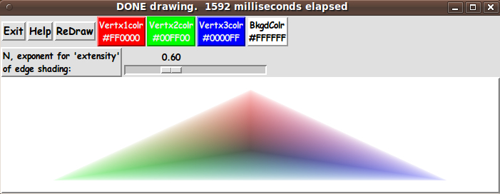
In my other 'shading metric' scripts above, I devised a scalar 'color-shading-metric' --- 'v' --- at each pixel point x,y that is within the rectangle/super-ellipse/super-formula/donut shape --- where v is between 0 and 1.

And the value of v goes to 1.0 at the boundary of these shapes --- and is zero in the middle of the shape.

Then v and (1-v) are applied to a user-selected background color and a user-selected 'fill' color for any pixel within the shape --- to get a 'weighted-average' of the user-selected colors, for the shaded-color at a given pixel x,y.

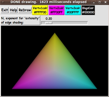
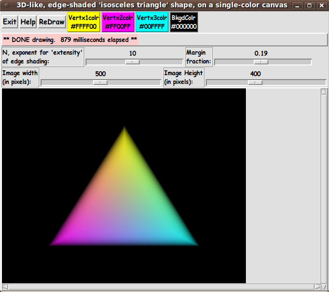
For the triangle of the script on this page, we use the barycentric coordinates of any pixel within the triangle --- to formulate our 'shading metric'.

For a given pixel x,y, let us say its barymetric coordinates are (L1,L2,L3) where L1 + L2 + L3 = 1.

Note that at the edges (and vertices) of the triangle, at least one of the 3 barymetric coordinates is 0.

Let us say that we want our metric, v(x,y) = v(L1,L2,L3), to be 1.0 at the edges of the triangle. (This is helpful when we later use an 'extensity' exponent to make 'crisper' shading at the edges.)

Also, we want v to be a zero at the barycenter of the triangle.

Note that the 'barymetric center' of the triangle is at the point/pixel where (L1,L2,L3) = (1/3,1/3,1/3).

And when one looks at any point within the triangle which is not on that center, at least one of the coordinates is less than 1/3.

Note that the quantity u = 3.0 * min(L1,L2,L3) is 1.0 at the barycenter and is zero on the edges of the triangle.

We want the opposite for our scalar 'color-shading-metric'.

Based on these observations, for our 'color-shading-metric', we will use

v(x,y) = v(L1,L2,L3) = 1.0 - ( 3.0 * min(L1,L2,L3) )

Note that v is 1.0 on the edges (and vertices) of the triangle, it is 0.0 at the barymetric center, and it is between 0 and 1 at other points in the triangle.

So we have a suitable metric, v.


USING THE SHADING-METRIC:

At a point x,y, we determine the 'shaded color' at the point by using a color interpolated between


  1) Rbary,Gbary,Bbary --- 'color-bary', say --- which is 
     the barymetrically-determined color of the point/pixel x,y
     calculated as follows:

     Let the RGB values of vertex 1, 2, and 3 be
             (R1,G1,B1) and (R2,G2,B2) and (R3,G3,B3).
     Then
             Rbary = (L1 * R1) + (L2 * R2) + (L3 * R3)
             Gbary = (L1 * G1) + (L2 * G2) + (L3 * G3)
             Bbary = (L1 * B1) + (L2 * B2) + (L3 * B3)

     where L1,L2,L3 are the barymetric coordinates of (x,y).


  and


  2) a user-selected background color, 'color-bkgd', say.


We calculate the 'shaded color' at x,y by calculating a weighted average based on applying the factor v to 'color-bkgd' --- and applying (1 - v) to 'color-bary'. That is,

shaded-color = v * color-bkgd + (1 - v) * color-bary.

We actually calculate via formulas like

Rshaded = v * Rbkgd + (1 - v) * Rbary
Gshaded = v * Gbkgd + (1 - v) * Gbary
Bshaded = v * Bbkgd + (1 - v) * Bbary

Thus we will get an edge-shading (the 3D or 'soft edge' effect) for the triangle shape.

Actually, it turns out that v and 1-v give a rather washed-out (too gradual) shading effect.

It is better if we raise v to a power N and use v^N and (1 - v^N), where N can be taken to be an integer greater than or equal to 1.

This is easy to do in Tcl-Tk, by using the 'pow' (power) function.

It turns out we get rather pleasing 'crisp', shaded edges on the triangle when N is between say 6 and 12.


SOME POSSIBLE ENHANCEMENTS:
(See the '2016 Jan 07 UPDATE' below.)

  • ** Performance Improvement
    The code above puts colors in the Tk 'photo' structure pixel by pixel. I may be able to reduce the draw times (on the order of 1 to 10 seconds) down to less than a second --- if I build the entire image as a list-of-lists (a list containing lists of row-colors) --- and do one 'put' of the list into the 'photo' structure.

    Such a list would probably be on the order of 8 Megabytes in size.

    In the old days, that would have been a no-no. But since users typically are dealing with over a Gigabyte of free memory on their computers, 8 Megabytes is less than one percent of that un-used memory.

    Doing a single 'put', rather than a 'put' for each pixel of the rectangular 'photo' structure, is high on my list of enhancements --- if I live to re-visit this code.

  • ** Edge-Shading Improvement
    I have to admit that I was a little disappointed that the 'shading-metric' that I am using does not seem to give me the kind of control on the edge shading that I was hoping for. I was hoping to create a sharper fall-off into the background shading, near the edges of the triangle.

    (That has been fixed. See 2016jan07 'UPDATE' below.)

  • ** Non-Isosceles Triangles
    I could do something like use 'create oval' on the canvas to make circular markers over the vertices. Then bindings could be made on those markers so that the user can drag them where they would like the vertices to be after the next re-draw.

    I am not sure that spending time on this is worthwhile. If this utility proves to be more experimental than useful, then maybe it is better to put this kind of feature in a more general utility.

  • ** More Re-Sizing Controls
    In this intial implementation of this demo-and/or-utility, I allow the user to change the size and aspect-ratio of the isosceles triangle by simply changing the size of the containing window --- which causes the canvas to resize, and the image size is set to the size of the canvas.

    I could allow for more precise controls, including control of the margin of background color around the triangle, but, again, I am not sure that spending time on this is worthwhile.

    Re-sizing the triangle by changing the window size is probably sufficient for most uses of this demo-and/or-utility.

  • ** Other
    There are probably some other enhancements that I should mention here, but I just hit the bottom of my ideas-well.


    IN CONCLUSION:

    I would like to give my usual thanks to Ousterhout and the maintainers of the 'wish' interpreter for making possible all these mathematical and graphical utilities and experiments (that I have done and that are on my 'to-do' list).


    UPDATE 2016 Jan 07:

    I have addressed several of the 'possible enhancements' listed above:

    • better ('crisper') edge-shading

    • draw the image with a list-of-lists-of-row-colors --- in other words, with one 'put' for the entire image rather than a 'put' for each pixel (The performance improvement was not as dramatic as I expected.)

    • better image sizing controls --- via 2 scale widgets instead of by window resizing.

    • added control of the 'margin' size around the triangle.

    In the process, I added several 'scale' widgets to the GUI --- resulting in the GUI seen in the following image.

In particular, the following changes have been made to the Tk script:

  • Changed the way the scalar 'color-shading-metric' 'v' is calculated --- for 'crisper' edge shading. (I changed the discussion above, on this page, accordingly.)

  • Added 2 scale widgets for better control of size of the image area.

  • Added a scale widget for 'margin-fraction' --- to allow control of the background-color 'margin'.

  • Added a frame to hold a message line --- instead of using the title bar of the window, which is controlled by the desktop window manager.

  • Added scroll bars to the canvas.

  • Updated the 'Help' text.

The code that was available in a code-link above has been replaced with with the new code.

See the comments in the code, and the code itself, for details.

Bottom of this page with
Tcl-Tk Code for a GUI to
Draw a 3-color-gradient ISOSCELES-TRIANGLE
with color-shaded, 3D-like edges

--- a utility in the FE 'tkGooies' system,
in the 'IMAGEcreatorsShaded3D' group.

To return to a previously visited web page location, click on the Back button of your web browser a sufficient number of times. OR, use the History-list option of your web browser.
OR ...

< Go to Top of Page, above. >

Page history:

The code was created in 2013 --- and posted 2013 Sep 05 at http://wiki.tcl.tk/38676.

This FE web page was created 2014 May 10 --- as a backup and alternative to the wiki.tcl.tk page.

This page was changed 2015 Oct 07.
(Small changes.)

Page was changed 2015 Dec 03.
(Added note on 'barycentric' versus 'barymetric'.)

Page was changed 2015 Dec 30.
(Added some paragraphs and some links.)

Page was changed 2016 Jan 07.
(See the 2016jan07 'UPDATE' section.)

Page was changed 2019 Mar 01.
(Added css and javascript to try to handle text-size for smartphones, esp. in portrait orientation.)

Page was changed 2019 Jun 14.
(Specified image widths in percents to size the images according to width of the browser window.)


NOTE:
The code here MAY BECOME more 'up-to-date' than the code posted on the Tcler's Wiki ---
wiki.tcl-lang.org --- formerly wiki.tcl.tk.
The 2016jan07 'UPDATE' may not be posted there.